Understanding Variable Resistors: Types, Functions, and Applications Explained
Variable resistors are used to adjust circuit current and resistance. They can also change the characteristics of the signal generator, dim the light, start the motor, or control motor speed. This document outlines the types, features, and functions of variable resistors.
Variable Resistors Explained
Variable resistors, which allow for resistance adjustment, are used to regulate circuit current and resistance. They can also alter the characteristics of the signal generator, dim the light, start the motor, or control motor speed. Depending on the intended use, variable resistor materials can be metal wire, metal sheet, carbon film, or conductive liquid. For currents of general magnitude, metal variable resistors are commonly utilized. When the current is small, we select the carbon film type. The electrolytic variable resistor is the optimal choice for high current applications, where the electrodes are immersed in a conductive liquid. A potentiometer is a specialized variable resistor for measuring the magnitude of an unknown voltage or potential difference. It is a resistor with two fixed connectors and one connector with an adjustable brush. The potentiometer is frequently utilized for audio control.
What we will discuss:
|
1 Circuit Symbol of Variable Resistor |
|
|
2 Typical Structure of Variable Resistor |
|
|
3 Classification of Variable Resistor |
1) Film-type Variable Resistors |
|
2) Wire Wound Variable Resistor |
|
|
4 Physical Characteristics of Variable Resistor |
|
|
5 Basic Function of Variable Resistor |
|
|
6 Potentiometer--A Special Type of Variable Resistor |
1) Types of Commonly-used Potentiometer |
|
2) Use of potentiometer |
|
1 Circuit Symbol of Variable Resistor
Figure 1 illustrates the circuit symbol of the variable resistor. It is based on the ordinary resistor circuit symbol with an arrow to represent its variable resistance characteristics. Two fixed pins and one moving pin can be identified from the circuit symbol. This is the latest variable resistor circuit symbol specified by the national standard. The letters in RP represent the variable resistor.

Figure 1. Circuit Symbol of Variable Resistor
Many existing circuit diagrams do not use this circuit symbol but instead utilize the older circuit symbol depicted in Figure 2. This symbol effectively illustrates the concept of variable resistor adjustment and the actual circuit connection. Its moving pin is connected to a fixed pin, effectively short-circuiting a portion of the resistor body's resistance. The variable resistor's resistance value is then determined by the resistance between the moving pin and another fixed pin. The variable resistor in Figure 2 uses only two pins.
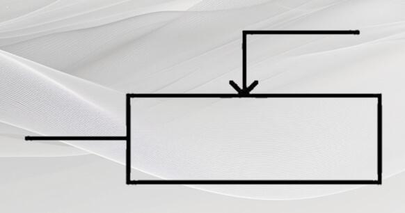
Figure 2. Old Circuit Symbol
Figure 3 shows the circuit symbol when the variable resistor is used as a potentiometer. It is obviously different from the one shown in Figure 2. Its three pins are independent. This is how to use the potentiometer of the variable resistor.
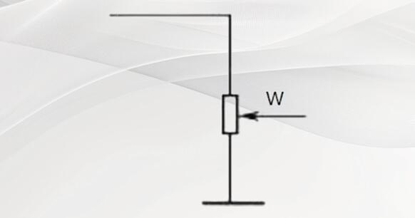
Figure 3. Potentiometer circuit symbol
2 Typical Structure of Variable Resistor
Understanding the structure of the variable resistor can easily analyze its working principle. Figure 4 shows the structure of a small-signal variable resistor. As can be seen from the figure, it mainly consists of a moving plate, a carbon film body and three pins. The three pins are two fixed pins and one movable pin. The moving plate of the variable resistor can be rotated left and right. And the contact points on the moving plate can slide on the resistor plate when we put a straight screwdriver into the adjustment hole and turn it.
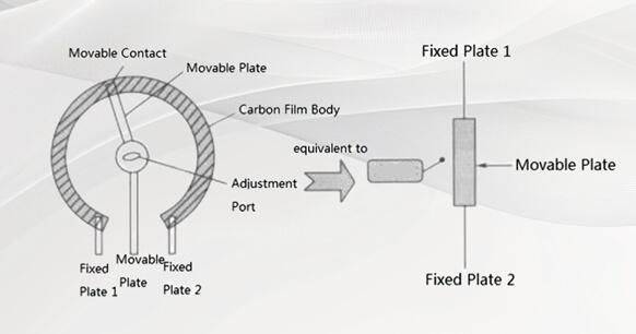
Figure 4. Structure of a Small-Signal Variable Resistor
Insert a straight screwdriver into the adjustment hole, and when the screwdriver is rotated clockwise or counterclockwise, the moving part will make corresponding rotational movements. When the moving part rotates counterclockwise (the moving plate moves upward in the equivalent circuit), the length of the resistor body between the fixed plate 1 and the moving plate decreases, and its resistance value decreases. As the length of the resistance body increases, its resistance value increases.
When the moving plate is rotated to the leftmost position (the top end), the resistance value between the fixed plate 1 and the moving pin is zero, and the resistance between the fixed plate 2 and the moving pin is the largest, which is equal to the nominal resistance of the variable resistor, which is also the resistance between the two fixed plates. When the moving plate slides to the rightmost position (lowest end), the resistance value between the fixed plate 2 and the moving pin is zero, and the resistance value between the moving plate and the fixed plate 1 is the largest, which is equal to the nominal resistance value.
Classification of Variable Resistors
The variable resistors can be divided into film type variable resistors and wire type variable resistors according to the materials;
1. Film-type Variable Resistors
The film-type variable resistor uses a rotary adjustment method and is generally used in small signal circuits, such as signal voltage. It's usually composed of a resistor body (synthetic carbon film), a movable contact (movable metal reed or carbon contact), an adjustment part, and three pins (or solder pads). Two of the fixed pins are connected to both ends of the resistor body, and the other pin (center tap) is connected to the moving contact. You can change the resistance between the center tap and the two fixed pins by turning the adjustment piece with a small straight screwdriver or by changing the contact position of the movable contact and the resistor.
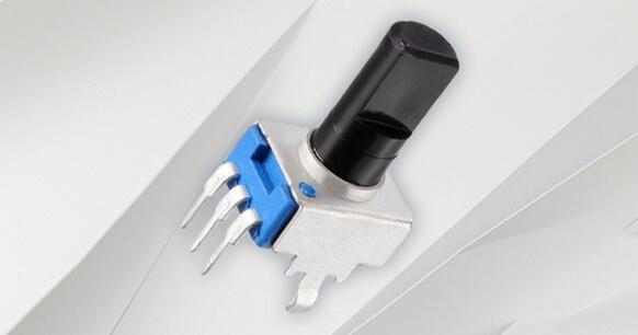
Figure 5. Carbon Film Variable Resistor
Film-type variable resistors are available in hermetic, semi-hermetic, and non-hermetic structures.
(1) Full-sealed Film Variable Resistor
A fully sealed film variable resistor is also called a solid film variable resistor. Its resistor body is made of carbon black, quartz powder, an organic binder and other materials, and then these materials are pressed into a plastic or epoxy resin substrate and polymerized by heating. The moving contacts use carbon contacts and the adjustment parts are made of plastic. The resistor body and the moving contact are sealed by a metal case, and there is an adjustment hole above, which has good dustproof performance and rarely has poor contact.

Figure 6. Quartz Powder
2) Semi-sealed film variable resistor
The manufacturing process of the resistor body of the semi-sealed film variable resistor and that of the fully sealed variable resistor is basically the same. The movable contact adopts a metal reed, and the outer plastic cover housing is sealed. When the plastic cover is rotated, the movable contact rotates with it. This type of variable resistor is easy to adjust, but its dust prevention performance is not as good as that of the fully sealed film type variable resistor.
3) Non-sealed film type variable resistor
Non-sealed film type variable resistor is also called chip type variable resistor. Its resistor body is made of a suspension fluid composed of carbon black, graphite, quartz powder, an organic binder, etc., which is coated on fiberboard or bakelite. The movable contact uses a metal reed, and there are adjustment holes on it, and no separate adjustment component is provided. It has poor dustproof performance, the contacts are susceptible to oxidation, and is prone to breakage due to poor contact with the synthetic carbon film.

Figure 7. Glass Fiberboard

Figure 8. Bakelite
2. Wirewound Variable Resistor
Wire-wound variable resistors belong to the power type resistors, which have the advantages of low noise, high temperature resistance, large current-carrying capacity, etc., and are mainly used for voltage or current adjustment of various low-frequency circuits.
High-power wire-wound varistor is also called sliding wire variable resistor. It is divided into axial porcelain tube type wire-wound resistor and porcelain disc type wire-wound resistor.
Low power wire-wound variable resistors include round vertical wire-wound variable resistors, round horizontal wire-wound variable resistors, and square wire-wound variable resistors, all of which are fully sealed package structures.
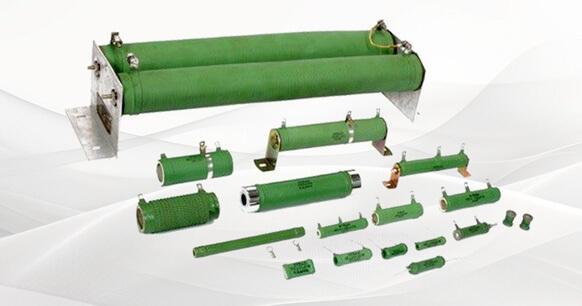
Figure 9. Wirewound Variable Resistor
The variable resistor can also be divided into vertical variable resistor and horizontal variable resistor according to the structure.
4 Physical Characteristics of Variable Resistor
Variable resistor is very different from ordinary resistor in appearance. It has the following characteristics. According to these characteristics, the variable resistor can be identified in the circuit board:
1) The volume of the variable resistor is larger than that of the general resistor, and at the same time, the variable resistor in the circuit is smaller than the general resistors, which can be easily found in the circuit board.
2) There are three pins in the variable resistor. These three pins are different. One is a movable pin and the other two are fixed pins. In general, the two fixed pins can be used interchangeably. The fixed and movable pins are not interchangeable.
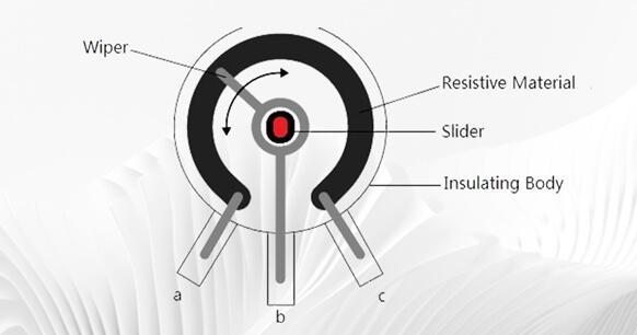
Figure 10. Pins in Variable Resistor
3)There is an adjustment hole on the variable resistor. Insert a straight screwdriver into this adjustment hole. Turn the screwdriver to change the position of the moving plate and adjust the resistance value.
4) The nominal resistance value can be seen on the variable resistor. This value refers to the resistance value between two fixed pins and is also the maximum resistance value between the fixed pin and the moving pin.
5) The vertical variable resistor is mainly used in small signal circuits. Its three pins are vertically down and vertically mounted on the circuit board. The resistance adjustment hole is in the horizontal direction.
6) Horizontal variable resistors are also used in small signal circuits. Its three pins are at 90° to the resistor and are mounted vertically on the circuit board with the resistance adjustment port facing upward.
7) The small plastic case variable resistor is smaller and has a round structure. Its three pins face down and the resistance adjustment hole faces up.
8) Variable resistors (wire-wound structures) for large power applications have large volumes, and the moving plate can slide left and right to adjust the resistance.
5 Basic Function of Variable Resistor
Variable resistor is a kind of resistance in the first place, it plays the role of resistance in the circuit. But it is different from ordinary resistance, its resistance value can be continuously changed within a certain range. In cases where the resistance value needs to be changed but not frequently, a variable resistor is recommended to be used.
It is an adjustable electronic component composed of a resistor body and a sliding system. The variable resistor is mainly used to control the current in the series circuit by changing its own resistance, thereby protecting some electrical components with current level requirements. It is generally used in circuits that do not require frequent adjustment and is mainly used to fix the resistance of the same value for the resistor. Variable resistors are also commonly used in small-signal circuits. Large-signal variable resistors are recommended in a few places, such as tube amplifiers.
Depending on the application, the resistive material of the variable resistor includes metal wire, metal sheet, carbon film, or conductive liquid. For currents of general magnitude, metal-type variable resistors are commonly used. When the current is small, it is better to use a carbon film type. When the current is large, the electrolytic type is most suitable. Due to the structure and use of variable resistors, the failure rate is much higher than that of ordinary resistors.
6 Potentiometer--A Special Type of Variable Resistor
In various electronic devices, we often see a component that can be adjusted manually. It is the potentiometer. Its function is to divide the voltage of the electrical signal applied to its two fixed ends in order to obtain the signal strength required by humans. If we compare the image of an electrical signal to a stream of water, the potentiometer works like the valve that controls the water level, which shows that the potentiometer plays an important role in electronic circuits.
There are many types of potentiometers, and the most commonly used are wire-wound, non-wire-wound, and electronic potentiometers used in audio circuits. However, no matter what form they're in, the main working principle is the same. Their commonly used symbols are shown in Figure 11.
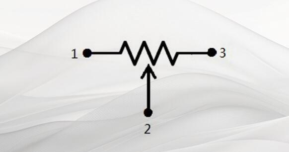
Figure 11. Potentiometer symbol
1) Types of Commonly Used Potentiometers
With the development of electronic technology, the types of potentiometers are increasing, and a "big family" with a variety of models and series has been formed.
According to the materials used to make the potentiometer, there are carbon film potentiometer, wire wound potentiometer and multi-turn potentiometer. From the use of the potentiometer, it can be divided into a rotary potentiometer, solid core potentiometer and fine tuning potentiometer, linear sliding potentiometer, and the electric potentiometer and stepping potentiometer developed with hi-fi technology. We can see the graphs of some commonly used potentiometers in Figure 12.
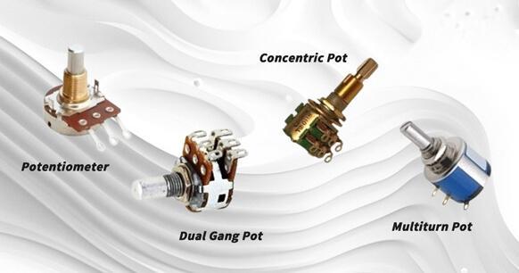
Figure 12. Types of potentiometers
With the increasing development of science and technology, people's demands on the parameters of electronic components are also increasing, and the precision of potentiometer manufacturing is also increasing. And as the fever for audio equipment continues to rise, people's demands for potentiometers are getting higher and higher. In order to synchronize the resistance values of dual-track potentiometers, a stepping potentiometer was developed. By connecting the resistors in series and in parallel, the dual-channel resistance can be synchronized to the maximum extent.
And with the development of remote control technology, electric potentiometers have also been developed, which are a special type of potentiometers specially made to match the remote control technology. The forward and backward rotation of the motor drives the gear to rotate the potentiometer. It can maintain the frequency characteristics of the original potentiometer and can be easily controlled, which is a promising electronic component.
2)Use of potentiometer
When we use a potentiometer, we must first recognize the symbol of the potentiometer in the circuit, as shown in Figure 13; secondly, we must find out the relationship between the circuit symbol and the actual potentiometer, which is the position of the center tap. Since the potentiometer is also a kind of resistor, we should also pay attention to its resistance and power value when using the circuit. Besides, the principle of use is the same as that of resistors. The difference is that potentiometers are used in schematics and are represented by "RP" ("w" in the old schematic).
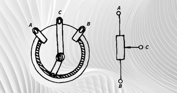
Figure 13. Potentiometer in circuit
The resistance shown on the potentiometer is the total resistance value of the potentiometer. Using Figure 13 as an example, if the resistance between A and B is 10K, the resistance between AC and BC will vary from 0 to 10K as we rotate the rocker arm.
Some beginners often find it difficult to find the center tap when using the potentiometer for the first time. To understand this problem, you just need to understand the relationship between the resistance of AC and BC and the position of the rotary axis.
We will use Figure 13 as an example. When the slider point C slides to the A end, the resistance of AC decreases and the resistance of BC increases. Conversely, if point A slides to point C, the resistance of AC increases and that of BC decreases. Therefore, in actual use, either use a multimeter to measure two ends of the potentiometer and rotate the shaft at the same time, the two ends with no change in resistance value are the AB ends, and the remaining end is the center tap.
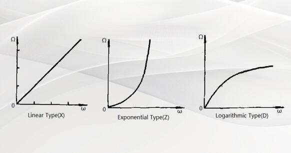
Figure 14. Resistance Changing Curve
In the process of using the potentiometer, its resistance value changes into three forms: exponential type (Z), logarithmic type (D), and linear type (X), as shown in Figure 14. Because their resistance values are different, their applications are not the same. For example, in the audio circuit, an exponential potentiometer should be used for volume control, and the linear type is suitable for a balanced potentiometer.
Conclusion
This article has introduced some basic knowledge about variable resistors, including the circuit symbol, structure, and function. In addition, two typical types of variable resistors一film-type and wire-wound type一and the potentiometer are explained to you in detail.


