
Comprehensive Guide to MAP Sensors: Location, Cleaning, and Differences Between MAP and MAF Sensors
MAP Sensor: The Manifold Absolute Pressure Sensor, or MAP sensor, is a working, structured, and type-specific device. The MAP sensor is an indirect air flow meter, and its signal is a critical input for the basic fuel injection control of the engine.
MAP Sensor - Manifold Absolute Pressure – Explained
Catalog
I. Introduction
II. Working Principle
III. Internal Structure
IV. Types of MAP Sensor
Ⅰ Introduction
The manifold absolute pressure sensor, or MAP sensor, is a device used to measure the pressure of the air in the engine's intake manifold. The MAP sensor is an indirect airflow meter, and its signal is a critical input for the basic fuel injection control of the engine. The MAP sensor is designed to sense changes in intake manifold vacuum and convert them into a voltage signal for the ECU, which then adjusts fuel injection volume accordingly. This process is affected by engine speed loads.
The MAP sensor is connected to the intake manifold via a vacuum tube. The MAP sensor location on the intake manifold is critical for its function, allowing it to accurately sense the pressure changes in the intake air.
In an electronic fuel injection engine, the MAP sensor is used to detect the intake air volume, which is referred to as the D-type injection system (speed density type). The MAP sensor detects the intake air volume indirectly, unlike the intake airflow sensor, which detects airflow directly. Additionally, it is subject to numerous external influences, which results in significant discrepancies in the detection and maintenance of intake airflow from the volume sensor.
II. Working Principle
This detection is possible because the MAP sensor located precisely behind the throttle can measure the pressure directly related to the engine's air intake. The MAP sensor detects the absolute pressure change in the manifold in accordance with the engine speed and load, subsequently converting this into a signal voltage and transmitting it to the engine control unit (ECU). The ECU controls the basic fuel injection volume according to the signal voltage.
There are a number of different types of MAP sensors, including varistor and capacitive types. The varistor type is widely used in D-type injection systems due to its advantages, including fast response time, high detection accuracy, small size, and flexible installation. These characteristics make the varistor type particularly appealing for precision tuning. Some tuners use various map sensor tricks to improve performance, such as adjusting the sensor's sensitivity to fine-tune engine response, taking full advantage of the sensor's capabilities to optimize engine performance. However, it's important for tuners to be aware that any adjustments to the sensor should be done with an understanding of the potential impacts on the engine's overall operation and emissions compliance.
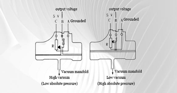
Figure 1
![]()
Figure 2
Figure 1: Connection between the varistor type MAP sensor and the computer Figure 2 illustrates the working principle of the varistor type MAP sensor. In Figure 1, R represents the strain resistance R1, R2, R3, and R4 shown in Figure 2. The components are connected in a Wheatstone bridge configuration and bonded to the silicon diaphragm. The silicon diaphragm is subject to deformation as a result of the absolute pressure within the manifold, which in turn affects the resistance value of the strain resistor R. As the absolute pressure in the manifold increases, the silicon diaphragm deforms more, resulting in a greater resistance change of the resistance R. This indicates that the mechanical change of the silicon diaphragm is converted into an electrical signal, which is then amplified by the integrated circuit and output to the ECU.
III. Internal Structure
The pressure sensor, integral to the MAP sensor's function, uses a pressure chip that incorporates a Wheatstone bridge on a silicon diaphragm. This setup is designed to detect and measure pressure changes within the intake manifold accurately. For optimal performance, it's crucial to clean the MAP sensor regularly, ensuring the diaphragm's precise deformation and accurate pressure readings, which are essential for the engine control unit to make precise fuel injection adjustments.
The pressure chip is the heart of the pressure sensor. All major manufacturers of pressure sensors utilize their own pressure chips. Some are manufactured by the sensor manufacturers themselves, while others are produced by outsourcing as dedicated chips (ASC) and the remaining option is to purchase general-purpose chips from professional chip manufacturers. Chips produced by sensor manufacturers or customized ASC chips are typically utilized exclusively in their own products. Such chips are highly integrated, often incorporating pressure chips, amplifying circuits, signal processing chips, EMC protection circuits, and those used to calibrate sensor output curves. The ROM is integrated on a chip, the entire sensor is a chip, and the chip is connected to the PIN pin of the connector through a lead.
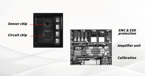
Figure 3. The internal structure of the pressure sensor based on MEMS technology
The pressure sensor, as shown in Figure 3, integrates other processing circuits, except for the sensor chip, into the circuit chip. Some pressure sensor manufacturers completely integrate the two into one.
This design and production process of pressure sensors is the practical application of MEMS technology (abbreviation of microelectromechanical systems). MEMS is based on 21st-century cutting-edge technology based on micro/nanotechnology. MEMS technology is the science of designing, processing, manufacturing, and controlling micro/nano materials. It can integrate mechanical components, optical systems, drive components, electrical control systems, and digital processing systems into a microsystem that is an integral unit. This microelectronic mechanical system can not only collect, process, and send information or instructions, but also take autonomous or external-instructed actions based on the acquired information. It employs a combination of microelectronics technology and micromachining technology (including silicon body micromachining, silicon surface micromachining, LIGA and wafer bonding, etc.) to produce a variety of high-performance, cost-effective sensors, execution devices, drives, and microsystems. MEMS technology leverages advanced technology to create microsystems and highlights the ability of integrated systems.
The pressure sensor is a prime example of MEMS technology, while the microelectromechanical gyroscope is another commonly used MEMS technology. A number of major EMS system suppliers, including Bosch, Denso, Conti, and others, have developed their own dedicated chips with similar structures. Advantages: high integration, small sensor size, small size of the sensor with small-size connectors, easy to arrange and install.
To maintain this service life, it's important to know how to clean a MAP sensor properly, which involves careful removal of dirt and debris without damaging the encapsulation.Large-scale mass production offers a cost-effective, high-yield, and excellent performance solution.
Some other manufacturers of MAP sensors utilize general-purpose pressure chips and then integrate the pressure chip, EMC protection circuit, and other peripheral circuits and connector PIN pins through the PCR board. As illustrated in Figure 4, the pressure chip is affixed to the reverse side of the PCB. The PCB is a double-sided printed circuit board.
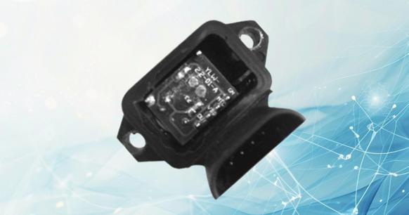
Figure 4. Use PCB board to integrate chips and circuits
The low integration level of this type of pressure sensor increases the cost of manufacturing materials. The PCB board does not have a fully sealed package, and the parts are integrated on the PCB board through the traditional soldering process, which increases the risk of virtual soldering. In an environment of high vibration, high temperature, and high humidity, it is important to protect the PCB.
IV. Types of MAP Sensor
The MAP sensor is designed to convert the pressure of the engine's intake pipe into a corresponding electrical signal. The engine electronic controller utilizes the signal to calculate the basic fuel injection time and determine the basic ignition advance angle. Pressure sensors are available in a variety of forms. According to the principle of signal generation, they can be divided into the following categories: piezoelectric, semiconductor varistor, capacitive, differential transformer, and surface elastic wave.
1. Semiconductor Varistor MAP Sensor
(1) Measuring Principle of Semiconductor Varistor Pressure Sensor
The semiconductor varistor pressure sensor employs the piezoresistive effect of semiconductors to convert pressure into a corresponding voltage signal. The principle is illustrated in Figure 5.
![]()
Figure 5. Measuring principle of semiconductor varistor pressure sensor
The semiconductor strain gauge is a sensitive element whose resistance value changes in response to tension or pressure. Attach the strain gauges to the silicon diaphragm and connect them to a Wheatstone bridge. When the silicon diaphragm is deformed by force, each strain gauge is pulled or compressed, resulting in a corresponding change in resistance. This, in turn, generates a voltage output from the bridge.
(2) Varistor MAP Sensor Structure
Figure 6 illustrates the composition of the semiconductor varistor MAP sensor. The pressure conversion element of the sensor incorporates a silicon diaphragm, which is subjected to pressure and deformation, thereby generating a corresponding voltage signal. One side of the silicon diaphragm is in a vacuum, while the other side is exposed to the pressure of the intake pipe. As the pressure in the intake pipe fluctuates, the silicon diaphragm undergoes corresponding deformation, resulting in the generation of a voltage signal that correlates with the intake pressure. As intake pressure increases, so too does the deformation of the silicon diaphragm, resulting in a corresponding increase in the output pressure of the sensor.
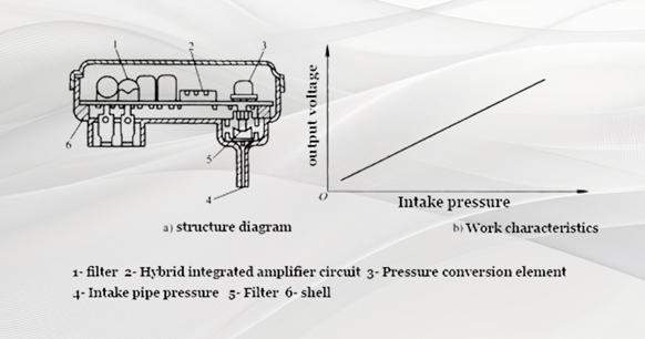
Figure 6. Structure of Varistor MAP Sensor
The semiconductor varistor MAP sensor offers excellent linearity, along with the benefits of a compact design, high precision, and responsive performance.
2. Capacitive MAP Sensor
(1) The Capacitive MAP Sensor's Measurement Principle
The capacitive pressure sensor employs a diaphragm to create a pressure-sensitive element with a variable capacitance. When the diaphragm is subjected to a force, its capacitance is altered in direct proportion. The sensor measuring circuit translates the capacitance change corresponding to the pressure into an electrical signal. The majority of capacitive pressure sensor measurement circuits are either frequency or voltage detection circuits, as shown in Figure 7.
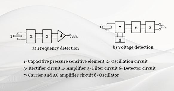
Figure 7. The measuring principle of the capacitive MAP sensor
1) Frequency detection type: The oscillating frequency of the oscillating circuit is adjusted in accordance with the capacitance value of the pressure-sensitive element. Following rectification and amplification, a pulse signal is generated whose frequency corresponds to the pressure.
2) Voltage detection type: The change in capacitance value of the pressure-sensitive element is modulated by the carrier and AC amplifier circuit, demodulated by the detector circuit, and filtered by the filter circuit to output a voltage signal corresponding to the pressure change.
(2) The Structure of the Capacitive MAP Sensor
Please refer to Figure 8 for a schematic diagram of the capacitive MAP sensor. The aluminum oxide diaphragm and the hollow insulating medium form a capacitive pressure-sensitive element with a vacuum inside, which is connected to the sensor hybrid integrated circuit. Once the sensor has detected the pressure of the intake pipe, the aluminum oxide diaphragm will deform in response to the pressure, resulting in a change to its capacitance value. Once processed by the hybrid integrated circuit, the electrical signal is outputted, corresponding to the change in intake pressure.
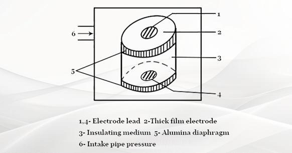
Figure 8. Structure of capacitive MAP sensor
Compared with the intake air flow sensor that plays the same role, the MAP sensor does not interfere with the air intake, and the installation position is flexible (the MAP sensor can be installed far away from the engine intake pipe using the vacuum tube guide). Therefore, MAP sensors are increasingly used in modern engine electronic control systems.
V. Output Characteristics
As the throttle opening changes, the vacuum, absolute pressure, and output signal characteristic curve in the intake manifold all change in concert.
Figure 9. MAP Sensor
The D-type injection system detects the absolute pressure in the intake manifold behind the throttle. The rear of the throttle reflects both the vacuum degree and the absolute pressure. Some people believe that the vacuum degree and absolute pressure are the same concepts. However, this understanding is incomplete. In the context of a constant atmospheric pressure (standard atmospheric pressure is 101.3 kPa), a higher vacuum in the manifold will result in a lower absolute pressure in the manifold. Vacuum is defined as atmospheric pressure minus absolute pressure in the manifold. Conversely, the higher the absolute pressure in the manifold, the lower the vacuum in the manifold. The absolute pressure in the manifold is equal to the atmospheric pressure outside the manifold, minus the vacuum. In other words, atmospheric pressure is equal to the sum of vacuum and absolute pressure. Once the relationship between atmospheric pressure, vacuum, and absolute pressure is understood, the output characteristics of the MAP sensor are clear.
During engine operation, a reduction in throttle opening will result in an increase in vacuum pressure within the intake manifold, a decrease in absolute pressure within the manifold, and a corresponding reduction in the output signal voltage. As the throttle opening increases, the vacuum of the intake manifold decreases, the absolute pressure in the manifold rises, and the output signal voltage grows. The output signal voltage from the MAP sensor is intricately linked to the conditions within the intake manifold: it is inversely proportional to the vacuum and directly proportional to the absolute pressure present. Understanding the relationship between vacuum and absolute pressure is important when performing MAP sensor cleaning, as this relationship affects not only the sensor's output but also the overall engine performance. Maintaining this balance through proper cleaning ensures that the sensor provides accurate readings, which are essential for the engine control unit to make informed decisions about fuel injection and ignition timing.


