
Comprehensive Guide to Selecting Aluminum Electrolytic Capacitors for Optimal Performance
This guide will provide an overview of the characteristics of aluminum electrolytic capacitors and offer guidance on how to select the most appropriate one for use in electrical designs.
Due to their high capacitance per volume and potential use in a wide range of electronic systems, aluminum electrolytic capacitors occupy a unique position among the various types of capacitors. They are suitable for use in a wide range of applications, including energy storage and the filtering of undesired AC frequencies. Due to their high capacitance values and low impedance values, these capacitors are frequently utilized in power supplies, inverters, and DC-DC converters.
The evolution of aluminum electrolytic capacitor technology is driven by the introduction of new materials and process improvements that enhance reliability and robustness, enabling operational lifespans of up to 20 years. When selected correctly, they are an essential component of the majority of electrical designs. It is important to understand what an aluminum electrolytic capacitor is and how to select the appropriate one for your projects.
What Is an Aluminum Electrolytic Capacitor?
A capacitor is composed of two electrically conductive material layers (electrodes) separated by a dielectric material (or insulator). Capacitors utilize an electric field generated by their internal structure to store energy when a current is supplied to charge the capacitor. The electrodes in an aluminum electrolytic capacitor are composed of aluminum foil. The two aluminum electrodes are separated by a conductive liquid, known as an electrolyte. An electrochemical reaction forms an oxide layer (Al₂O₃) on one of the electrodes (the anode), which serves as the dielectric in an aluminum electrolytic capacitor.
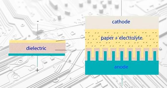
Figure 1. The construction of an aluminum electrolytic capacitor.
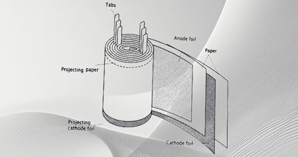
Figure 2. Another view of the construction of an aluminum electrolytic capacitor.
Electrical Characteristics
The construction and materials of aluminum electrolytic capacitors afford them a number of distinctive electrical characteristics, making them an optimal choice for a wide range of applications.
|
Characteristics |
Description |
|
Large Capacitance |
Aluminum electrolytic capacitors offer a high degree of capacitance per unit of volume for a given voltage rating, making them an ideal choice for a range of applications. |
|
High Voltage Rating |
Aluminum electrolytic capacitors are suitable for use in a wide variety of applications due to their high voltage rating. |
|
Energy Storage |
Aluminum electrolytic capacitors offer high-energy storage capabilities due to their large capacitance and high voltage rating. |
Advantages of Aluminum Electrolytic Capacitors
The key advantages of aluminum electrolytic capacitors are as follows:
Firstly, electrolytic capacitors have high volumetric efficiency, meaning they offer a higher capacitance per volume than any commonly available capacitor. In certain applications, aluminum electrolytic capacitors are the only viable option. When selected and designed into the circuit correctly, this advantage can be optimized.
Another advantage of aluminum electrolytic capacitors is their availability in a range of high voltage ratings. Aluminum electrolytic capacitors with a DC voltage rating of 600V are widely available, making them suitable for use in a diverse range of applications.
The combination of high capacitance and high voltage in aluminum electrolytic capacitors offers another significant benefit: energy storage. The energy stored in a capacitor can be calculated using the following equation:

Equation 1. Energy stored in a capacitor (U = Joules, C = Capacitance, V = Voltage)
The energy stored in a capacitor increases in line with the capacitance and exponentially with the voltage.
Selecting a Capacitor for Power Applications
A fundamental understanding of aluminum electrolytic capacitors is the first step in choosing the optimal one for a power electronics design. The following are the key design considerations:
Voltage Rating / Derating
Capacitor voltage ratings provide a safe operating range for a capacitor, ensuring optimal performance and reliability. Operating within these ratings ensures the capacitors are not damaged and allows them to function for an extended period of time. Aluminum electrolytic capacitors are typically used to provide bulk capacitance to power supply voltage rails.
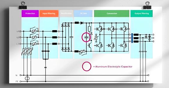
Figure 3. Example frequency converter circuit.
Due to their polarised nature, aluminium electrolytic capacitors are only suitable for use in DC voltage applications, such as the example circuit following DC rectification. It is important to select a capacitor that is suitable for the load conditions of the application. This should take into account the operating voltage, surge and transient voltages, ripple current, ambient temperature, cooling conditions and expected useful life. It is not advisable to select a voltage rating that exceeds the required level, as higher voltage ratings tend to coincide with higher ESR. In applications with high ripple currents, higher ESR can cause significant issues.
Equivalent Series Resistance
Engineers are taught about ideal capacitors at an early stage of their training, but it is important to recognise that real-world capacitors are not ideal. It is possible to model real capacitors as if they were ideal capacitors with a few additional parasitic elements.
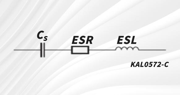
Figure 4. Equivalent circuit of a real capacitor.
In this illustration, CSCS represents the ideal capacitive component of the equivalent series circuit. Please note that the capacitance measured will depend on both the temperature and the frequency of the signal used to make the measurement. The ESR represents the resistive component of the equivalent series circuit. ESR is dependent on both frequency and temperature, and is related to the dissipation factor by the following equation: The ESR can be calculated as follows: ESR=tanδ/ω∗CS. In this equation, tan δ represents the dissipation factor, while ω is the frequency applied. Finally, ESL represents the inductive component of the equivalent circuit. It is a result of the internal design of the capacitor and its terminal or lead configuration.
In the context of power supply applications, it is essential to prioritize the assessment of equivalent series resistance (ESR). The alternating current (AC) portion of the current seen by the capacitor, or the ripple current, causes power to be dissipated by the ESR in the capacitor. This effect is dependent on the frequency of the ripple current. An increase in ESR results in greater power dissipation within the capacitor, leading to elevated heat generation and a reduction in the capacitor's operational lifespan. It is not necessary to select the lowest possible ESR when specifying a capacitor for a power supply design. However, it is recommended to select an ESR rating that works with the ripple current in the design.
Ripple Current
In electrical engineering, the term "ripple current" is used to describe the root mean square (RMS) value of the alternating current that flows through a device as a result of any pulsating or ripple voltage. The power losses resulting from this ripple current induce self-heating of the capacitor. The maximum permissible value of the ripple current is dependent on several factors, including ambient temperature, ESR at the frequency of the AC signal, thermal resistance (which is primarily determined by the surface area of the capacitor, or heat dissipation area), and the effectiveness of the cooling system in place. Furthermore, this is limited by the ripple current capability of the contact elements.
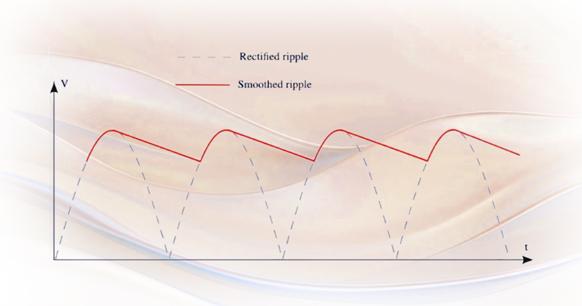
Figure 5. A rectified voltage smoothed by capacitance.
The rated ripple current (IAC, RIAC, R) is typically specified at the upper category temperature and the reference frequency.
Given that thermal stress has a significant impact on the capacitor's lifespan, it is crucial to consider the heat generated by the ripple current as an important factor affecting the capacitor's useful life. In light of these thermal considerations, it may be necessary, in certain circumstances, to select a capacitor with a higher voltage or capacitance rating than would normally be required by the respective application.
Surge, Transients, and Reverse Voltages
It is important to note that capacitors are sensitive to transients, overvoltages, and reverse voltages. Typical aluminum electrolytic capacitors are capable of withstanding surge voltages that are 10 percent higher than their rated value for short periods of time. Some capacitor types are capable of withstanding voltage pulses in excess of the surge voltage. Given the varying requirements of different applications, it is advisable to select the capacitor design that meets the specific application specifications. It is always advisable for engineers to have a good understanding of the transients and overvoltages that may occur in capacitors used in their designs.
Aluminum electrolytic capacitors are polarized components that are susceptible to catastrophic failure in the event of reverse voltage exposure. It is advisable to connect a diode where necessary to prevent voltages of opposite polarity. Reverse voltages of up to 1.5V can be tolerated for a period of less than one second, making diode protection a viable option. It is important to note that aluminum electrolytic capacitors are not designed to withstand reverse voltages, even at levels of ≤1.5V, whether in continuous or repetitive operation.
Cooling
The useful life values stated in our datasheets are applicable to aluminum electrolytic capacitors with natural cooling, whereby the heat generated in the winding is dissipated through the case. Additional cooling measures, such as a heat sink or forced ventilation, can be employed to increase the permissible ripple current and prolong the useful life.
As a significant amount of heat is dissipated through the base of the case, a heat sink connected to the capacitor base provides the most efficient cooling solution. TDK offers specially designed versions of high-voltage capacitors with screw or snap-in terminals that can be mounted on a heat sink to ensure optimal heat transfer from the heat generation area via the base of the case to a heat sink.
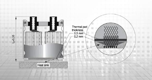
Figure 6. Aluminum electrolytic capacitor with heatsink.


