Comprehensive Guide to Capacitor Symbols and Their Functions in Circuits

Introduction
Definition of a Capacitor
A capacitor is an electronic component that stores charge and electrical energy, enabling the release of the stored charge in a circuit. It is also commonly referred to as a capacitor or simply "capacitor." The primary function of a capacitor is to store and release electrical charge, which makes it a highly versatile component in electronic circuits.
Capacitors are typically constructed with an insulating material (commonly referred to as a dielectric) positioned between two conductive plates, which are typically made of metal. The dielectric material used between the conductive plates can be air, ceramics, polyester film, aluminum electrolyte, and so on. One of the conductive plates is connected to the positive electrode of the circuit, and the other is connected to the negative electrode of the circuit. When a voltage is applied to the capacitor, a positive charge is accumulated on the positive plate and a negative charge is accumulated on the negative plate. The charge is distributed in the dielectric, resulting in the formation of an electric field.
Explanation of a Capacitor Symbol
In a circuit diagram, the capacitor symbol represents the physical capacitor element. The symbol for a capacitor typically comprises two parallel lines or plates, indicating the two conductive plates that constitute a physical capacitor. The two plates are separated by a non-conductive substance, known as a dielectric.
In circuit diagrams, the parallel lines can be drawn either vertically or horizontally, as required. In the case of polarized capacitors (such as electrolytic capacitors), one of the lines may be curved, or the plus "+" symbol may be used on the positive side.
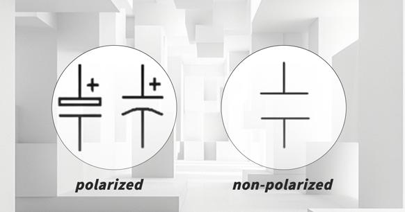
Figure 1: Symbol Representation of a Capacitor in a Circuit Diagram
It should be noted that the symbol does not depict the actual physical layout of the component. However, it serves to illustrate the component's function, namely the storage and release of electrical charge, as well as its connection within the circuit. The presence of this symbol in a circuit diagram signifies the inclusion of a capacitor at that particular point.
Types of Capacitor Symbols
Polarized Capacitor Symbols
There are two main types of capacitor symbols: polarized capacitor symbols and non-polarized capacitor symbols.
Polarized capacitors have two pins that clearly indicate positive and negative polarity. This polarity cannot be reversed when the capacitor is in use. The most common polarized capacitors are electrolytic capacitors, which can be further divided into aluminum electrolytic capacitors and tantalum electrolytic capacitors based on the materials used.
Polarized capacitors are capable of filtering out clutter or interference waves in a circuit, which is why they are also known as smooth filter capacitors. The physical shape and circuit graphic symbols of polarized capacitors are illustrated in the accompanying figure.
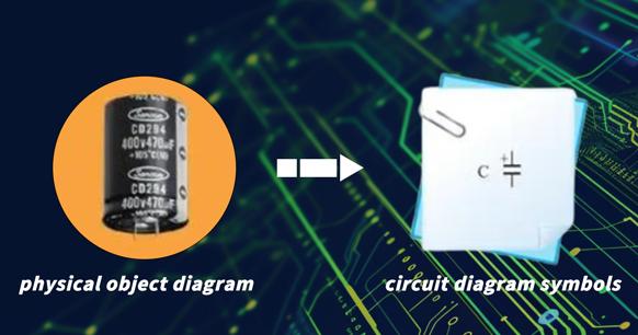
Figure 2: Polarized Capacitor and Its Circuit Graphic Symbols
Non-Polarized Capacitor Symbols
The two pins of the non-polarized capacitor have no positive or negative polarity, allowing the two pins to be exchanged and connected when in use.
Please refer to the figure for an illustration of the physical shape and circuit graphic symbols of non-polarized capacitors.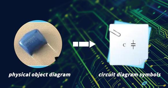
Figure 3: Non-polarized capacitor and its circuit graphic symbols
Due to the characteristics of the material and production process, the capacitance of non-polarized capacitors is fixed. This quality distinguishes them as fixed capacitors. The non-polarized capacitor primarily fulfills the roles of coupling, smoothing, filtering, phase shifting, and resonance within the circuit.
Non-polarized capacitors are available in a variety of forms, including colored ring capacitors, paper capacitors, porcelain dielectric containers, mica capacitors, polyester capacitors, glass glaze capacitors, and polystyrene capacitors. The circuit graphic symbols of these capacitors are identical, yet their physical shapes and characteristics vary.
Variable Capacitor Symbol
A variable capacitor is a device that allows the user to manually adjust the capacitance value. This is frequently employed in tuning circuits, such as those utilized in radios. The symbol for a variable capacitor is similar to that of a fixed capacitor, but with an arrow through one of the plates to indicate that it is adjustable. The symbol can be represented as follows:
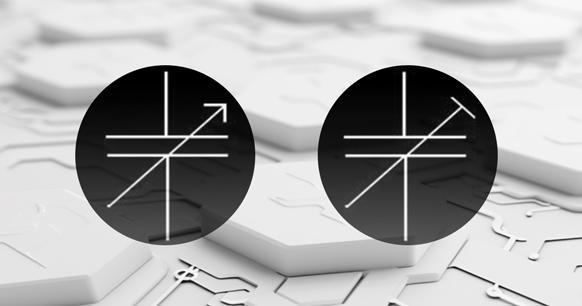
Figure 4: Graphic symbol for variable capacitors
Capacitor Symbols on a Multimeter
Explanation of How a Multimeter Measures Capacitance
A multimeter measures capacitance by charging a capacitor with a known current, measuring the resulting voltage, and then calculating the capacitance using the formula C=Q/V, where Q is the charge stored in the capacitor and V is the voltage across the capacitor. This process is automated within the multimeter.
Understanding the Capacitor Symbol on a Multimeter
The capacitor symbol on a multimeter is typically represented by a capital letter "F," which stands for Farads, the unit of capacitance. Some multimeters may utilize a symbol analogous to that employed in circuit diagrams (two parallel lines), though this is less prevalent.
To measure capacitance, simply switch the multimeter dial to the setting with the capacitor symbol. The probes should then be connected to the capacitor in question, ensuring that the correct polarity is observed if the capacitor is polarized. The multimeter display will then show the capacitance of the capacitor in Farads (or, in some cases, in microfarads, µF).
Variations in Capacitor Symbols
Differences in American and European Symbols
Please note that there are slight differences between the capacitor symbols used in circuit diagrams according to American and European standards.
In the United States, the following symbol is used: In American notation, a fixed (non-polarized) capacitor is typically represented by two parallel lines. A polarized capacitor, such as an electrolytic capacitor, is frequently represented by a plus symbol on the positive side, or a curved line representing the negative plate and a straight line representing the positive plate.
In European notation, a fixed (non-polarized) capacitor is typically represented by a straight line and a curved line parallel to each other. The representation of a polarized capacitor is the same as in American notation.
Other International Variations
In other parts of the world, the capacitor symbols used may adhere to either American or European conventions, or sometimes a combination of both. It is also not uncommon to see the symbol of a variable capacitor (an arrow through one of the plates) used to represent a generic capacitor in some regions. It is imperative to refer to the legend or key provided with the circuit diagram to understand the symbols used.