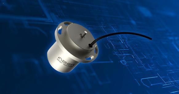
Understanding RVDT: Construction, Operation, and Applications
The Rotary Variable Differential Transformer (RVDT) is a transformer that detects angular displacement of the conductor. This is the type of electromechanical transducer that provides angular displacement of the input equal to the linear output.
In this video, we will discuss the construction and operation of the RVDT, which can be used to measure rotary displacement.
What is RVDT?
RVDT Catalog
1 Introduction
2 Construction of RVDT
3 Operation of RVDT
4 Advantages of RVDT
5 Disadvantages of RVDT
6 Applications of RVDT
1 Introduction

RVDT
An RVDT (Rotary Variable Differential Transformer) is used to calculate the angular displacement of the test circuit. The RVDT plays an important role in aircraft, aerospace, and medical sciences. It is used to measure or vary angular displacement and stabilize the system. Its operation is similar to that of the LVDT, where the cam-shaped center rotates with the help of the shaft between the windings. This article will provide a brief overview of the RVDT sensor, including its full form, operating theory, case studies and tests, advantages, disadvantages, and real-time implementations.
2 Construction of the RVDT
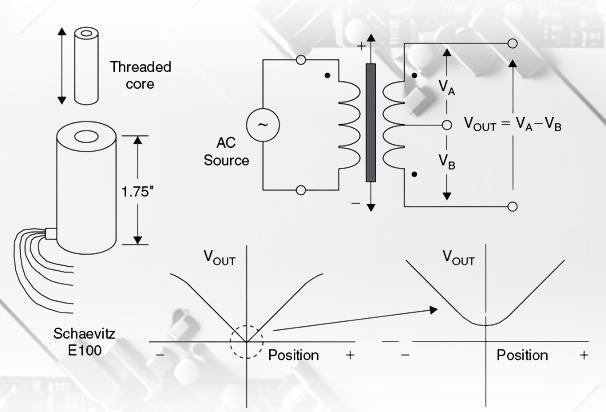
As shown in the figure below, the circuit diagram of the RVDT consists of one main winding and two secondary windings. The physical parameters and design aspects of the RVDT core have been chosen to ensure that the angular displacement produced by the coil is linear with respect to the induced mutual inductance between the primary and each secondary coil. As it is driven by an external electrical source and converts angular displacement into electrical signals, it is often considered a passive transducer. Other names for the RVDT include angular position sensor, differential transducer, RVDT transducer, inductive sensor, etc. The device's efficiency and longevity are enhanced by its brushless continuous rotation feature.
3 Operation of the RVDT
Let us assume that the secondary voltage of the RVDT transformer is Es21 or Es22.
The sensitivity of the RVDT is determined by the parameter 'G'.
The angular displacement of the shaft is determined by theta (ϴ), which is given by the following equation:
θ=G*(Es21-Es22)/(Es21-Es22))
The secondary stress is calculated using the following equation:
Es22=Es22±G*θ
The differential output voltage on the secondary side is given by
∆Es22=2*G*θ
The RVDT operates on a similar principle to the LVDT, with collective induction at its core. When the primary windings of the RVDT are subjected to an AC excitation voltage of approximately 5-15V and a frequency range of 50-400Hz, a magnetic field is generated within the heart. This field is then induced into the secondary winding, creating a magnetic current equal to the magnetic field generated.
The difference between the voltage induced by the secondary windings is the net RVDT output voltage.
The output voltage E o is usually equal to
Eo=Es21-Es22
The theory of RVDT operation is divided into three situations with respect to the inner core position. The RVDT experiment is carried out on the same basis.

RVDT Shape, Circuit Diagram and Characteristic Curve
Case 1: When the core is correctly located in the zero position (equilibrium state)
In this instance, the positioning of the core is precisely centered due to the placement of two secondary windings. The flux linkage between the secondary windings (S21 and S22) is equal and zero (Eo=Es21-Es22=0), which is the net induced EMF. The core remains stationary, and therefore, it is considered a normal base value for the calculation of angular differences.
Case 2: Clockwise core rotation
In this state, the RVDT primary coil is connected to an external power source, inducing an EMF in the circuit. Due to the flux connection around the center, it begins to rotate in a clockwise direction.
S21 is superior to S22. This indicates that the EMF generated in S21 is greater than that generated in S22. Therefore, a positive Es21-Es22 would indicate that S21 is greater than S22, resulting in a full differential voltage. The primary voltage is in phase with the output voltage.
Case 3: Counterclockwise core rotation
The generation of EMF occurs within the RVDT circuit. Due to the greater flux linkage through S22 compared to S21, the core continues its rotation in a counterclockwise direction. This indicates that the EMF generated in S22 is greater than that of S21, with Es22 being greater than Es21. As a result, the total voltage difference is negative (Es22-Es21=-ve). The main voltage and output voltage are 180 degrees out of phase (in phase opposition).
4 Advantages of RVDT
(1). Robust, rugged and suitable for extremely harsh environments
The RVDT is designed for a longer product life and is therefore durable in design. It can be used in a wider range of operating environments. It is suitable for measuring angular displacement in applications that include vital and rugged wear. It is able to withstand harsh conditions such as severe vibration, shock, and overload.
(2). Cost-effective
If you are looking to reduce the cost of calculation, this is the optimal choice. The majority of the project is covered by the cost, especially if the budget is limited. Along with the robustness, the cost of the RVDT is lower than other sensors.
(3). Fewer and quicker repairs
A reduced number of electronic parts allows for simpler RVDT construction. This eliminates the need for complicated circuits or special auxiliary parts to achieve angular throughput, reducing repair costs for small components.
(4). Compact in volume
By reducing the number of electronic components in the RVDT, we have been able to reduce the overall size of the unit to a comparatively small area. This has allowed us to create a sensor that can interface with external devices in a limited space, which has expanded the number of applications that we can offer.
(5). Non-contact design
RVDT eliminates performance issues related to physical integrity and friction generation due to wear and tear within the structure, as there is no mechanical interaction between the components.
5 RVDT Disadvantages
The following disadvantages are associated with the RVDT:
(1). It is limited to applications where high-precision sensors are required.
(2). An external AC power supply is required to achieve output functions.
(3). It is not superior to digital output applications.
6 Applications of RVDT
The following outlines the applications of the Rotary Variable Differential Transformer (RVDT).
RVDT applications offer a number of advantages, making them a popular choice in heavy-duty production facilities in industries such as oil and gas, aerospace, and more.
The standard RVDT implementations are as follows:
(1). Testing the angular acceleration of control actuators and propeller navigation in aircraft and avionics applications.
(2). Developing intelligent fuel control systems for engines.
(3). Controls and wiring in the cockpit.
(4). To measure angular displacement and extract movements of the hand, legs, and other momentary sections in robotics.
The market research survey on Rotary Variable Differential Transformer applications indicates that the factors driving the RVDT to the global level are increased automation and the growing number of industrial automation applications. The need for portable research facilities, machine tools, and expanded robotics applications will continue to drive this trend in the future. As the RVDT-powered devices evolve, it will be interesting to see what the next generation of technology will bring.


