5G Era Antenna Design: Challenges, Innovations, and Future Trends for Smartphones

Cell phone antennas are devices that receive signals for cell phones. While old cell phones had protruding antennas, most new cell phones have integrated antennas hidden within the body of the device.
Catalog
1. Introduction
2. Concept explanation
3. The development of cell phone antennas
4. Cell phone antennas in the 5G era
5. Difficulties of cell phone antenna design in the 5G era
1. Introduction
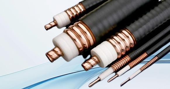
The cell phone antenna is a crucial device on mobile phones used to receive and transmit electromagnetic waves. Whether you are making calls, sending text messages, or playing online games, each of these daily communication activities relies on the functionality of the phone's antenna module. It is important to recognize that without an antenna, a smartphone would essentially function as a stand-alone game console.

cell phone antenna
The radio transmitter transfers radio frequency signal power to the antenna through the feeder (cable), which in turn radiates it as electromagnetic waves. Upon reaching the receiving location, the electromagnetic wave is captured by the antenna (receiving only a small part of its power) before being sent to the radio receiver through the feeder. From this process, it becomes clear that antennas play a critical role in transmitting and receiving electromagnetic waves; without them, there would be no means for radio communication.
2. Concept explanation
Antenna input impedance
The input impedance of the antenna is the impedance value obtained from the interface between the transceiver and the antenna looking at the antenna end. This value has a great impact on the radiation efficiency of the antenna, the in-band gain fluctuation of the antenna, and the power capacity of the antenna front-end.
Operating frequency and operating bandwidth
The bandwidth of an antenna is the range of the frequency band that satisfies all the parameters of the antenna. The operating frequency refers to all frequencies within the bandwidth of the antenna. The operating bandwidth is limited by several indicators, so the bandwidth with the narrowest-bandwidth should be selected. In mobile phone antennas, the bandwidth limited by the pattern bandwidth, polarization bandwidth and other factors is greater than the impedance bandwidth. Therefore, in mobile phone antennas, the operating bandwidth of the antenna is generally defined as the bandwidth range that meets the required standing wave.
Beam pattern
The antenna beam pattern is used to describe the relationship between the energy radiated by the antenna and any position in the space. The relative intensity or absolute intensity of the electromagnetic wave radiated by the antenna at each position in the space can be obtained by the pattern. There is no doubt that the horizontal pattern of the mobile phone antenna is required to be omnidirectional. In fact, the beam pattern of the mobile phone antenna is not important, and it is mainly in the use of the mobile phone. At this time, the radiation characteristics of the mobile phone antenna are not the same as that of the single antenna. The pattern of the cell phone antenna only requires that the horizontal plane be approximately omnidirectional.
Directivity and antenna gain
The directivity of an antenna is related to its beam pattern, so the directivity is also a function of the azimuth Angle, which is defined as follows. D(θ,ψ)= [radiation intensity of the antenna in the (θ,ψ) direction] / [radiation intensity of the omnidirectional antenna] In practical applications, because the radiation efficiency of the antenna itself must be considered, the directivity is usually replaced by the size of the antenna gain, and the relationship between the two is:
G (θ,ψ) =eD(θ,ψ)
Among them, the radiation efficiency of antenna is related to the amount of energy lost in the process of electromagnetic wave radiation.
All possible energy losses in the process of energy transmission and reception include: the energy reflection caused by the impedance mismatch of the antenna input, the energy loss caused by the material of the antenna itself at high frequency, and the energy consumed in the propagation medium. The gain of the mobile phone antenna does not represent the efficiency of the mobile phone when it is used: the real indicator of the antenna gain characteristics should be the average effective gain of the antenna, which is related to the use environment and use mode of the mobile phone antenna, the structure of the mobile phone, and the design mode of the mobile phone.
3. The Evolution of Cell Phone Antennas
The earliest large cell phone antennas were external, low-frequency analog signal antennas. During the 2G period, NOKIA introduced built-in antennae made from thin stainless steel sheets. As technology advanced and cost reduction became a priority, printed circuit boards (FPC) began to be utilized. FPC is known for its soft material and ability to conform to curved surfaces, offering advantages in terms of space utilization over traditional metal antennas. Even today, FPC antennas remain the mainstream antenna technology.
With the advancement of technology, the LDS antenna technology has emerged. This involves directly engraving the antenna with a laser on a specially processed plastic molding material. This technology is commonly found in current mid-to-high-end cell phones.
MIMO Technology
Multi-input Multi-output (MIMO) is an abstract mathematical model that describes a multi-antenna wireless communication system. It utilizes multiple antennas at the transmitting end to independently send signals, and employs multiple antennas at the receiving end to restore the original information through space-division multiplexing.
Without increasing bandwidth or total transmission power consumption, MIMO can significantly improve data throughput and transmission distance. The fundamental concept of MIMO is to leverage the spatial freedom provided by numerous transmitting and receiving antennas to enhance spectrum efficiency in wireless communication systems, resulting in higher transmission rates and improved communication quality.
MIMO technology can be applied in wireless communication networks for communicating with base stations, as well as in WiFi networks for communicating with wireless routers. The notation A*B MIMO is typically used to indicate the number of antennas; for example, 2*2 MIMO denotes 2 channels of transmission and 2 channels of reception, with a theoretical transmission capacity twice that of SISO.
It is anticipated that future 5G networks will see an increased use of MIMO technologies in terminals.
4. Cell phone antennas in the 5G era
The size remains constant while the quantity increases.
The antenna plays a crucial role in wireless communication equipment as it is responsible for transmitting and receiving electromagnetic wave signals. Typically, the antenna is a wire with a specified length that can be manufactured on PCB and FPC.
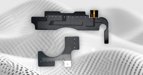
FPC Antenna
The length of the antenna is closely related to the wavelength of the wireless signal, often needing to be 1/4 or 1/2 of the electromagnetic wavelength. For instance, in the 2G era, the electromagnetic wavelength for the 900Mhz frequency band was 20-30cm, while the antenna size was approximately 7.5cm.
With current communication bands like 4G (0.8-2.6GHz) and primary frequencies used by 5G being below 6GHz, there will be minimal changes in cell phone antennas' sizes using Sub-6G frequency bands for 5G technology—remaining at centimeter levels.
However, to meet increased speed requirements, additional antennas or MIMO technology will be employed by 5G. For example, utilizing a configuration such as 4×4 MIMO with four transmitter antennas and four collector antennas.
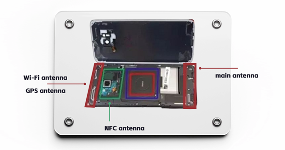
The increase in antenna numbers will necessitate rearranging multiple antennas' shapes which will impose new demands on cell phone back covers and wiring to achieve better efficiency. The Huawei Mate30 Pro has a total of twenty-one antennae—fourteen of which are dedicated to supporting 5G technology.
5.Difficulties of cell phone antenna design in the 5G era
There are two 5G frequency bands: low frequency and high frequency. The low-frequency band operates at 3~5Ghz, similar to the current 4G band, and can utilize existing antenna designs with an increased number of antennas to meet the 5G transmission rate requirements. MIMO multi-antenna technology can be employed in the low-frequency band to address this need. However, this solution is not effective in the high-frequency band due to the shorter wavelength resulting in greater transmission attenuation.
In the 5G high-frequency band, with communication wavelengths of only about 10mm (millimeter wave), there is a "proximity effect" where fingers and faces in front of the millimeter-wave antenna may cause signal drop or even shield the signal directly.

The challenge becomes even greater when considering today's popular full-screen design for mobile devices. Antenna design becomes particularly challenging as it needs to radiate 360° while avoiding metal interference within a certain range known as the "clearance zone". This clearance area is often located on the "chin" of a phone, but with full-screen designs reducing this area significantly and covering it entirely with metal screens, antenna design faces very high requirements.
Specifically for 5G millimeter waves which are highly susceptible to interference from metals, at least a 1.5mm headroom is required. When hands or faces block the phone, causing signal interference, it will start seeking out alternative frequency bands with lower bit error rates. Therefore, proper consideration must be given to antenna installation locations from the outset when designing a 5G terminal.
The challenges posed by 5G antenna design are likely to compel manufacturers to abandon the metal back cover and modify the shape and size of the fuselage. If you need a visual representation of this, simply take a look at Moto Z3's latest 5G module, and you will find your answer.
However, the complexity of antenna design in the 5G era does not necessarily mean that smartphones will become unattractive. The smartphone market in the 5G era may undergo a new round of restructuring, with truly innovative manufacturers standing out and continuing to offer consumers aesthetically pleasing and functional products.
While 5G antenna design is indeed challenging, there are viable solutions available. Currently, industry experts generally favor antenna array (multi-antenna unit) designs. This involves composing an antenna system using numerous identical single antennas arranged according to specific rules.
Presently, millimeter-wave antenna arrays for 5G primarily rely on phased arrays. Implementation methods include AoB (Antenna on Board), where the antenna array is located on the system motherboard; AiP (Antenna in Package), where the package containing the antenna array is situated inside the chip; and AiM (Antenna in Module), where the antenna array and RFIC form a module. At present, AiM is considered as being most prevalent.
Millimeter-wave antenna arrays utilizing AiM typically employ complementary radiation beams—such as broadside radiation or end-fire radiation—and various types of antennas—like patch antennas—to achieve broader spatial coverage. By appropriately designing the feed point of these antennas, dual-polarization coverage (vertical and horizontal polarization) can be achieved, significantly enhancing millimeter-wave signal range and coverage capabilities.
The switching of multiple antenna arrays may also lead to another issue. Transitioning from an antenna array with weaker performance to a gap between an antenna array with higher performance could result in a significant loss of data and a decrease in user connection experience. As such, the decision to switch the antenna array and how to minimize the transition time requires collaboration between hardware engineers and software engineers, which can serve as a test of the manufacturer's capabilities.
Furthermore, the design of small-sized phased antenna arrays helps reduce the internal space and clearance area required for 5G antennas. This enables a more compact body design and a higher screen-to-body ratio. In October 2020, Qualcomm introduced The QTM052 millimeter wave antenna module, which is 25% smaller than its predecessor, further reducing the space occupied by 5G antennas on mobile phones.
The advent of the 5G era presents new challenges for smartphone manufacturers not only in terms of antenna design but also in network layout, ecosystem development, and application scenarios based on 5G technology. Fortunately, challenges also bring opportunities. In this new era, truly capable manufacturers will undoubtedly distinguish themselves and achieve significant progress in their respective fields.