What is a variable capacitor?

What is a variable capacitor?
A variable capacitor is a type of capacitor that can have its capacitance adjusted within a specific range. This adjustment is achieved by changing the relative effective area between the pole metal plate or the distance between the plates, resulting in a corresponding change in capacitance. Typically used as a tuning capacitor in radio receiving circuits, it comes in two main types: Air dielectric variable capacitors and Solid dielectric variable capacitors. Variable capacitors are widely utilized in tuning and amplification, frequency selective oscillation, and various other circuits.
Variable capacitor
1. Variable Capacitor Introduction
Variable capacitors are capacitors whose capacitance can be adjusted within a certain range.
They typically consist of two sets of pole plates insulated from each other: a fixed set called the stator and a movable set called the rotor. Multiple rotor sets may be combined on the same shaft to create coaxial variable capacitors, commonly referred to as double, triple, etc. Variable capacitors are equipped with a long handle that allows for adjustment by pulling wires or dials. The typical shape is as follows:
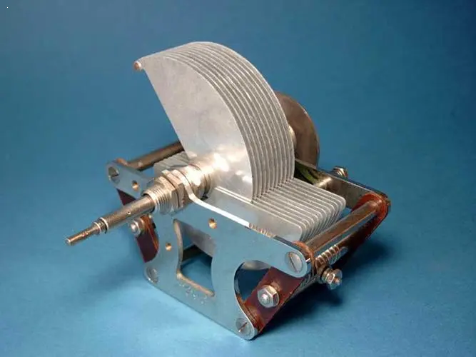
Figure1. variable capacitor
2. Capacitor Identification
The value of a capacitor is typically identified on the body by a number or alphanumeric code, and in some cases, it may also be indicated by a color-coded ribbon. The label on the capacitor provides important parameters such as capacitance value, rated voltage, and tolerance.
In certain situations, capacitors may not explicitly state the unit of capacitance. In these instances, the default units are inferred from the given values based on empirical identification methods. Additionally, some capacitors use a 3-digit notation where the first two digits represent the capacitance value and the third digit indicates the multiplier or number of zeros after the second digit. For example, 103 denotes 10,000 pF.
Some types of capacitors use designations like WV or WVDC to specify their rated voltage while others may omit this information. In cases where it is omitted, manufacturers provide guidance for determining the rated voltage. Capacitor tolerances are commonly expressed as an allowable percentage deviation (e.g., ±10%). Furthermore, temperature coefficient is denoted in parts per million (ppm) and consists of either P or N followed by numerical values. For instance, N750 represents a negative temperature coefficient of 750 ppm/°C whereas P30 indicates a positive temperature coefficient of 30 ppm/°C. The designation NPO signifies that both positive and negative temperature coefficients are zero, resulting in negligible change in capacitance with varying temperatures. Certain types of capacitors may also feature color-coded ribbons for easy identification purposes.
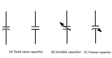
Figure2. circuit symbols for a fixed capacitor and a variable capacitor
(a)depicts a graphic symbol representing a fixed-value capacitor in a circuit, with both types being commonly used. In some variations of capacitors, the left curve in the figure typically denotes the outer plate (i.e., the end near the outer package), which is usually marked by a colored stripe adjacent to the wire connected to the plate.
(b) illustrates the symbol for a variable capacitor, incorporating an arrow through the plate to differentiate it from a fixed capacitor. Smaller trimmer capacitors are generally represented by the symbol on the right, with arrows indicating their variable plates.
3. Classification of Variable Capacitors
Variable capacitors can be categorized into air dielectric variable capacitors and solid dielectric variable capacitors based on the dielectric materials utilized.
1) Air Dielectric Variable Capacitor
The electrode of an air dielectric variable capacitor consists of two sets of metal sheets, with one set being fixed as the stator and the other set being rotatable as the rotor. Air serves as the medium between the moving plate and the fixed plate.
When the moving plate of an air-dielectric variable capacitor is rotated to screw all moving plates into the fixed plate, its capacitance reaches its maximum value. On the contrary, when the moving plate is completely rotated out from the fixed plate, its capacitance becomes minimal.
Air medium variable capacitors are further subdivided into air single-connected variable capacitors and air double-connected variable capacitors. Generally employed in radios, electronic instruments, high-frequency signal generators, communication equipment, and related electronic devices.
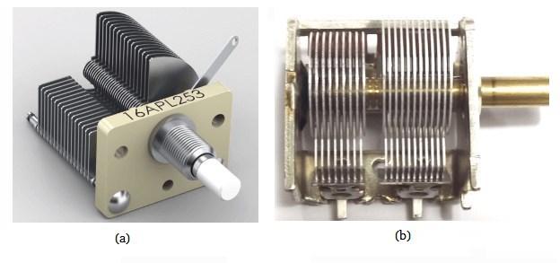
Figure3. (a) air single-connected variable capacitors (b) air double-connected variable capacitors
2) Solid Dielectric Variable Capacitor
The solid dielectric variable capacitor utilizes a mica sheet or a plastic film (such as polystyrene and other materials) as the medium between the moving plate and the fixed plate, with irregular semi-circular metal plates comprising the moving piece and the fixed piece. The shell is made of transparent plastic. Its advantages include small size and lightweight design; however, it has disadvantages such as producing large amounts of noise and being susceptible to wear and tear.
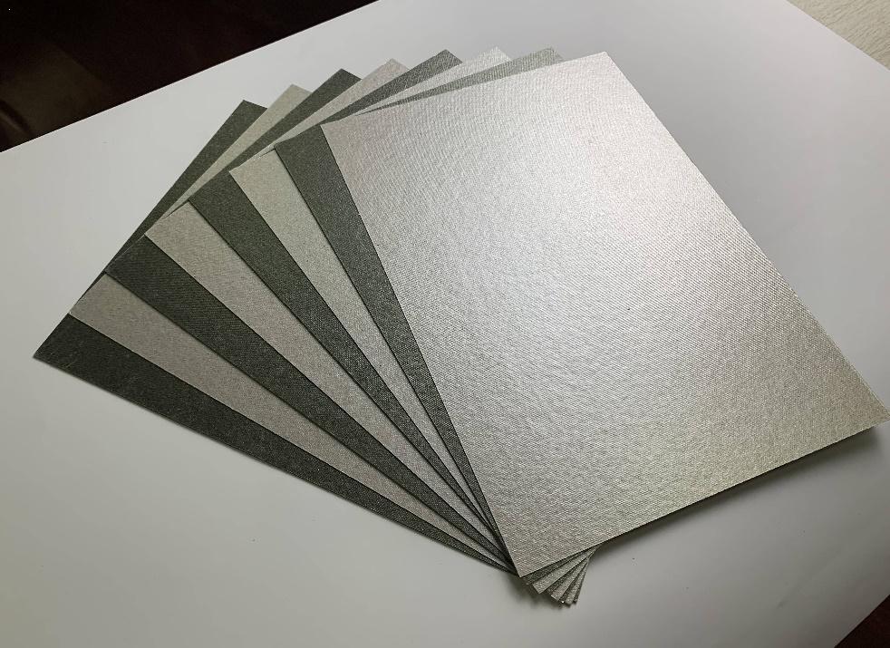
Figure4. mica sheet
Solid dielectric variable capacitors are categorized into three types: sealed single-connected variable capacitors, sealed double-connected variable capacitors (which consist of two sets of rotor, stator, and dielectric that can rotate coaxially and synchronously), and sealed four-connected variable capacitors (equipped with four sets of the rotor, stator, and dielectric).
Sealed single-connected variable capacitors are predominantly utilized in simple radios or electronic instruments. Sealed double-connected variable capacitors find application in transistor[s1] radios, related electronic instruments, and electronic equipment. On the other hand, sealed four-connected variable capacitors are commonly employed in AM/FM multi-band radios.
4. Structure and working principle of variable capacitors
1) The structure of a variable capacitor
The electrodes of a variable capacitor, regardless of its type, consist of two sets of metal sheets insulated from each other. In the following discussion, we will use the earliest air-dielectric variable capacitor as an example to illustrate its structure and working principle: As depicted in Figure, one group of electrodes is fixed and serves as the stator, while the other group is movable and called the rotor. The air acts as a medium between the moving plate and the fixed plate. When the moving plate of an air-dielectric variable capacitor is rotated so that all movable pieces are inserted into the fixed plate, it results in maximum capacitance; whereas when the moving piece is completely rotated out of the fixed plate, it leads to minimum capacitance.
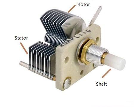
Figure5. Air variable capacitor
In practical applications, the movable plates of multiple variable capacitors can be mounted on a common rotating shaft to create a coaxial variable capacitor. These variable capacitors are equipped with a long handle that can be adjusted using a pull-wire or dial. Consequently, air medium variable capacitors are classified into two types: air single-connected and air double-connected variable capacitors.
2) What is the function of a variable capacitor?
The primary purpose of a variable capacitor is to modify and regulate the resonance frequency of a circuit loop. It is commonly utilized in tuning and amplification, frequency-selective oscillation, and various other electronic circuits.
i. Resonance Circuit
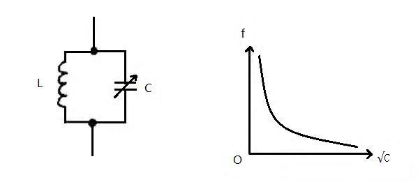
Figure6. Resonance circuit
As depicted in the diagram, the LC resonant circuit can alter the resonant frequency by adjusting the capacitance of the variable capacitor C. The resonance frequency is inversely proportional to the square of the capacitance, as indicated by this formula:
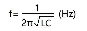
ii. Frequency-Selective Oscillation
The capacitor is employed in oscillators to allow for continuous adjustment of oscillation frequency within a specific range. In high-frequency signal generators, adjusting a single-pole variable capacitor C enables modification of output signal frequency as required.
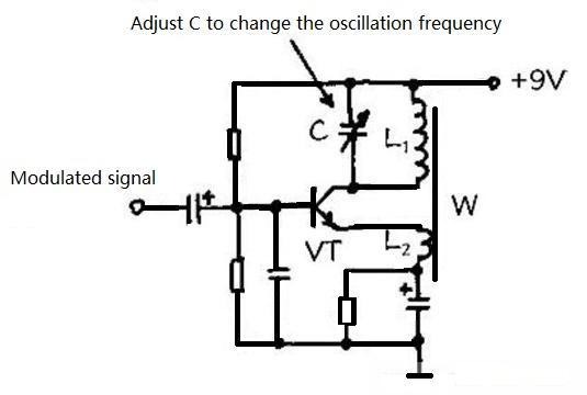
iii. Tuning
Variable capacitors are frequently used in radio tuning loops to facilitate selection of radio stations. Illustrated below is a super-heterodyne radio frequency conversion stage circuit incorporating one section (C1a) from double-variable capacitor C1 connected to the antenna output circuit, while another section (C1b) is linked to the local oscillation circuit. Adjusting these two sections alters reception at synchronized frequencies. Additionally, trimmer capacitors C2 and C3 are utilized for calibrating antenna input and local oscillation circuits' frequencies respectively.
Figure8. Tuning
5. Trimmer capacitors
A trimmer capacitor, also known as a semi-variable capacitor, is a type of variable capacitor that serves the purpose of micro-adjustment. It is commonly utilized for precise capacitance adjustment without the need to change the capacitance during use. The primary requirement for trimmer capacitors in a circuit application is to maintain the reliability of a specified capacitance value.
There are various types of trimmer capacitors based on the dielectric material utilized, including air trimmer capacitors, porcelain-trimmed trimmer capacitors, organic film trimmer capacitors, and mica trimmer capacitors. These are often used as compensation or correction capacitors within tuning and oscillation circuits. Trimmer capacitors enable adjustments within a small range, with some being capable of being fixed to a specific capacitance value after adjustment, hence earning them the moniker "semi-trim" capacitors. Adjustment of a trimmer capacitor involves altering the distance or area between its two plates.
A typical trimmer capacitor consists of one or two sets of small metal plates sandwiching a dielectric material in between them. The design resembles that of a variable capacitor but lacks handles for manual adjustment; instead requiring adjustment through screwdrivers only. As such, semi-variable capacitors find common use in applications where frequent adjustments are not necessary and are employed primarily as compensation or correction components within different tuning and oscillation circuits.
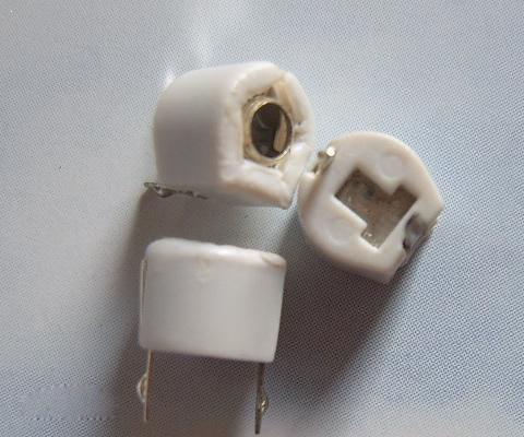
Figure9. The shape of a semi-variable capacitor
Trimmer capacitors can be categorized into ceramic trimmer capacitors and organic film trimmer capacitors. Ceramic trimmer capacitors consist of two plates made of silver porcelain, with the bottom plate being fixed and the top plate being movable. The movable plate is able to rotate with the shaft. Due to the fact that the area covered by silver on both plates is less than a semicircle, the capacitance can be adjusted by rotating the shaft.
On the other hand, organic thin-film trimmer capacitors utilize polyester film as a medium, along with single-layer or multi-layer phosphor copper sheets serving as fixed and moving plates. These capacitors have a smaller volume compared to porcelain-based trimmer capacitors.
6. VI How to test a variable capacitor?
The capacitance of the variable capacitor is generally very small and cannot be measured with a multimeter. However, it can be determined whether there is a short circuit or leakage between the moving and fixed plates, as depicted in the figure below.
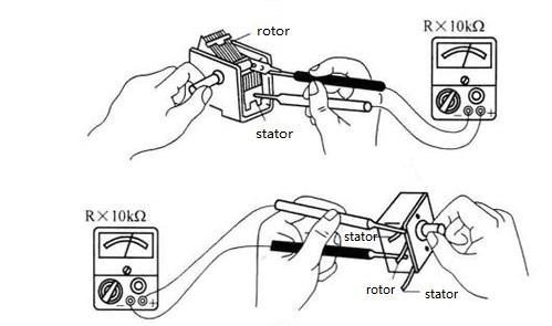
Figure10. Variable capacitor test
The gap between the moving plate and the fixed plate of the variable capacitor is very small, making it susceptible to short-circuiting upon contact. The multimeter's electric block can be used to detect whether the variable capacitor is touching the chip.
During testing, place the two test leads of the multimeter on the rotor and stator of the capacitor, and slowly rotate the shaft of the capacitor back and forth. If the meter hand remains stationary, it indicates that there is no contact. If it points to zero ohms when rotated to a certain angle, it means that there is contact between the plates. After confirming contact, check if there are any irregularities in distance between the moving plate and fixed plate. Any skewed or distorted plates can generally be straightened with a thin blade if they have been affected by external factors. In cases where one or two sets of fixed plates are bent or deflected to one side, this may be due to loosening of the fixed board bracket rubber board or solder desoldering at both ends of such plates.
Electrostatic noise refers to a series of "chatter" noises that appear in radio speakers during tuning caused by turning the variable capacitor shaft during station tuning. If no short circuit is found in soldered connecting wires on the fixed piece then we say this electrostatic noise was caused by electrostatic effect itself. When organic sealed variable capacitors generate electrostatic noise connect their rotor and stator pins to a 12V DC power supply then rotate their rotors several times thus eliminating its inherent electrostatic noise issues.