Understanding USB Type-C: Pin Signals and PCB Layout Guide

USB Type-C is a smaller-volume USB interface standard than Type-A and Type-B. It can be used on a PC (master device) as well as external devices (slave devices, such as mobile phones).
EEVblog #1323 - PCB Layout Review & Analysis
Topics covered in this article:
1. What is USB-Type-C
2. USB 2.0 differential pair
3. Power and ground pins
4. RX and TX pins
5. CC1 and CC2 pins
6. VCONN pin
7. SBU1 and SBU2 pins
8. USB power supply
9. PCB design and wiring requirements
1. What is USB-Type-C?
1) The Meaning of USB-Type-C
USB Type-C is a smaller-volume USB interface standard than Type-A and Type-B. It can be used on a PC (master device) as well as external devices (slave devices, such as mobile phones).
USB Type-C is comprised of 4 pairs of TX/RX split lines, 2 pairs of USBD+/D-, a pair of SBU, 2 CCs, 4 VBUS, and 4 ground wires. USB-C is a relatively new standard that allows for high-speed data transmission of up to 10 gigabits per second and power of up to 100 watts. These features have the potential to make USB-C a truly global connector for current electronics.
2)Function introduction
The USB-C interface serves three purposes:
The connection interface is reversible for convenience. The plug can be oriented in relation to the socket due to the interface's architecture.
It complies with the USB 2.0, USB 3.0, and USB 3.1 Gen 2 specifications. Furthermore, the device has an alternate mode that enables it to accept third-party protocols such as DisplayPort and HDMI.
The interface enables devices to negotiate and select the appropriate power flow.
3. Signal Diagram
The USB Type-C connector has 24 pins. Please refer to Figures 1 and 2, which illustrate the pins of the USB Type-C socket and plug, respectively.

Note: The characteristics of the USB Type-C interface are as follows:
A. Compact: In contrast to the conventional USB Type-A interface, the innovative USB Type-C interface is significantly smaller, measuring only 8.3*2.5mm. This makes it an ideal choice for increasingly compact computing devices. The USB Type-C interface can withstand 10,000 cycles of insertion and removal when used in equipment.
B. High data transmission speed: USB 3.1 specification support, data transmission speed up to 10 Gbps;
C. Non-directional: The USB Type-C interface, like the Apple Lightning interface, has no directional constraints, allowing for simple, convenient pairing by inserting both the front and back sides. This improves the USB interface's overall simplicity of use.
D. Robust power supply capability: The USB 3.1 Type-C interface can deliver up to 100W of power output, and the USB Type-C interface offers two-way power supply. This allows for simultaneous charging of the device and external devices, while also charging the device. The time required for the process can be reduced by up to two-thirds.
E. High scalability: USB Type-C is capable of carrying audio and video signals, as well as supporting a number of audio and video output interfaces, including HDMI, DVI, and VGA. It also has the capacity to expand to 4K resolution.
2. USB 2.0 differential pair
For USB 2.0 connections, the D+ and D- pins are differential pairs. The socket contains two D+ pins and two D- pins.
However, due to the coupling of these pins, only one USB 2.0 data differential pair can be used. The redundant design is solely for the purpose of providing a reversible connector.
3. Power and ground pins
The VBUS and GND pins serve as the power and signal return channels. The default VBUS voltage is 5V, although the standard permits the device to negotiate and choose a different VBUS voltage than the default. VBUS can be configured to operate at a voltage of up to 20V, allowing for power transmission. Furthermore, the maximum current can be increased to 5A. Consequently, USB Type-C is capable of delivering up to 100W of power.
High power flow may be beneficial for charging large devices such as laptop computers. Figure 3 illustrates a RICHTEK example in which a buck-boost converter is employed to generate the voltage required by the laptop.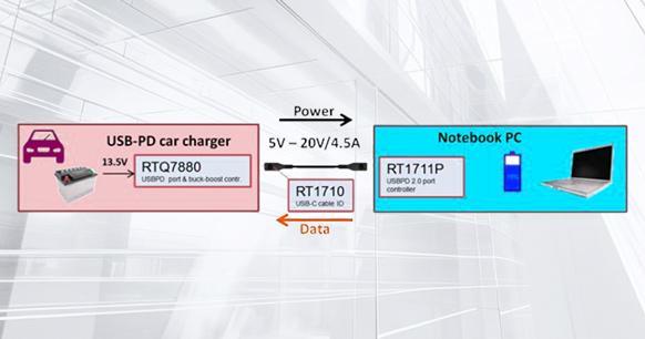
The USB Type-C standard offers greater versatility than its predecessor due to its power transfer technology, which adapts the power level to the needs of the load. A single USB-C cable can be used to charge both a smartphone and a laptop
4. RX and TX pins
RX differential pairs and TX differential pairs are divided into two groups.
In the case of USB 3.0/USB 3.1 protocols, one of the two RX pairs and the TX pair can be utilized. The multiplexer is necessary to redirect the data on the utilized differential pair across the cable correctly, as the connector is reversible.
Please be aware that while the USB Type-C port is capable of supporting the USB 3.0/3.1 standard, USB 3.0/3.1 is not included in the USB Type-C minimum feature set. In other instances, such as when utilizing the USB Type-C capabilities of standby mode and USB power supply protocol, the USB 3.0/3.1 connection can be employed in lieu of the RX/TX pair. Furthermore, these routines can utilise all available RX/TX differential pairs.
Furthermore, these pins can be utilized for Power Delivery and Alternate Mode communication.
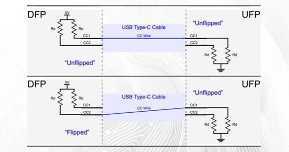
Figure 4 illustrates how the CC1 and CC2 pins display the socket/plug orientation. DFP stands for downstream-facing port, which serves as a host or power source during data transfer. An upstream-facing port (UFP) is a device that is linked to a host or power consumer.
The Rp resistor pulls up the CC1 and CC2 pins in DFP, while Rd pulls them down in UFP. In the event that the cable is not attached, the source will detect a logic high level at the CC1 and CC2 pins. By connecting the USB Type-C cable to the 5V power supply, a current route from the power supply to the ground is established. As the USB Type-C cable has only one CC wire, only one current path is produced. As illustrated in the upper diagram of Figure 4, the CC1 pin of the DFP is connected to the CC1 pin of the UFP.
5. CC1 and CC2 pins
These pins are utilized to configure the channel. These pins serve a variety of purposes, including detecting cable connections and removal, socket/plug orientation detection, and current broadcast. Furthermore, these pins can be utilized for Power Delivery and Alternate Mode communication.
The CC1 and CC2 pins display the socket/plug orientation as shown in Figure 4. In this diagram, DFP stands for downstream-facing port, which serves as a host or power source during data transfer. An upstream-facing port (UFP) is a device that is linked to a host or power consumer.
The Rp resistor serves to pull up the CC1 and CC2 pins in DFP, while the Rd resistor pulls them down in UFP. If the cable is not attached, the source will detect a logic high level at the CC1 and CC2 pins. Connecting the USB Type-C cable to the 5V power supply establishes a current route from the power supply to the ground. As the USB Type-C cable has only one CC wire, only one current path is produced. As illustrated in the upper diagram of Figure 4, the CC1 pin of the DFP is connected to the CC1 pin of the UFP.
Consequently, the DFP CC1 pin voltage is below 5 V, yet the DFP CC2 pin remains at a logic high level. Consequently, the cable connection and direction can be determined by monitoring the voltage on the DFP CC1 and CC2 pins.
In addition to conveying information about the cable's orientation, the Rp-Rd path is also used to send information about the source's current capability. The power consumption (UFP) monitors the voltage on the CC line to achieve this. The source is capable of supplying the default USB power supply of 500 mA and 900 mA for USB 2.0 and USB 3.0, respectively, when the voltage on the CC line is at its lowest value (approximately 0.41 V). The source is capable of generating 1.5 amps of current when the CC line voltage is approximately 0.92 volts. The maximum CC line voltage is around 1.68 volts, corresponding to a 3-amp source current capability.
6. VCONN pin
USB Type-C is designed to provide ultra-fast data transfer speeds and high levels of power flow, as previously stated. These qualities may necessitate the use of special cables with a chip inside that is electronically tagged. Furthermore, some active cables include re-drive chips to enhance the signal and compensate for the cable's loss. In such cases, a 5 V, 1 W power supply to the circuit inside the wire can be used to power the VCONN pin. Figure 5 provides a visual representation of this concept.
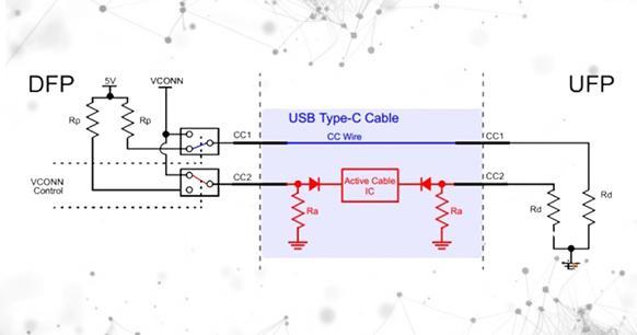
As illustrated, the active cable exerts a downward force on the CC2 pin through the Ra resistor. DFP can still determine cable orientation by monitoring the voltage on the DFP CC1 and CC2 pins because Ra is different from Rd. Once the cable's direction has been determined, the channel configuration pin corresponding to the "active cable IC" will be linked to a 5 V, 1 W power supply to supply power to the circuit inside the cable. For example, the effective Rp-Rd route corresponds to the CC1 pin in Figure 5. Consequently, the CC2 pin is connected to the VCONN power source.
7. SBU1 and SBU2 pins
Please be advised that these two pins correspond to the low-speed signal path used exclusively in standby mode.
8. USB powered
Let us now turn our attention to the USB power supply and standby mode, after we have gained a better understanding of the USB-C standard.
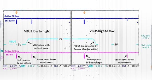
Devices that use the USB Type-C standard can negotiate and select an acceptable degree of power delivery across the interface, as previously described. These power negotiations are conducted via the USB Power Delivery protocol, which is the single-wire communication on the CC line previously mentioned. Figure 6 depicts an example of a USB power supply. In this scenario, the receiver issues a request to the source, which then adjusts the VBUS voltage as needed. First and foremost, a 9V bus is a prerequisite. Once the source bus voltage has stabilized at 9V, the source will transmit a "power ready" message to the receiver. The receiver then requests a 5V bus, which is provided by the source, which then sends the "power ready" message once more.
It is important to note that the term "USB power supply" encompasses more than just a power supply. Other agreements, such as those for standby mode, are also carried out using the power supply protocol on the standard CC line.
9. PCB design and wiring requirements
The Type-C interface layout and wiring requirements are as follows:
1) The ESD common-mode inductance device should be placed as close to the USB interface as possible. The order of placement is ESD-common mode inductance-resistance and capacitance. It is also important to maintain a 1.5mm spacing between ESD and USB. Please consider the situation of post-welding when determining the distance between these components.
2) The Type-C interface has four sets of differential signals (RX/TX1-2), two sets of D+/D- differential signals, and a total of six pairs of differential lines. It is required that differential signal lines be situated in close proximity to at least one ground plane, with both sides of the plane being preferable.
3) It is important to ensure that the line spacing of the differential line is consistent throughout the routing process. It is advisable to keep the differential line as long as possible. If the length of the two lines differs, you may wish to consider drawing a serpentine line to increase the length of the shorter line.
4) CC1/CC2 are two key pins with a multitude of functions. They are used to detect the connection, distinguish the front and back, and distinguish DFP and UFP. In other words, they are used to determine the master-slave configuration of Vbus and the surface. Therefore, when routing, it is important to ensure that the Vbus and surface are thickened.