Complete Guide to Varistors: Understanding Definition, Function, and Testing Techniques

A varistor is a device with a non-linear volt-ampere characteristic. When the voltage applied to the varistor is lower than its threshold value, the current flowing through it is extremely small, which is equivalent to a resistor with infinite resistance, and vice versa. The most common varistor is a metal-oxide varistor (MOV).
What is a Varistor?
1 What is a Varistor?
A varistor is a device with a non-linear volt-ampere characteristic. It is used to clamp the voltage when the circuit is subjected to overvoltage and absorb excess current to protect sensitive devices. It is also called a "voltage-dependent resistor" or VDR. The material of the resistor body of a varistor is a semiconductor, so it is a variety of semiconductor resistors. The "zinc oxide" (ZnO) varistor, which is now widely used, is composed primarily of the divalent element zinc (Zn) and the hexavalent element oxygen (O). From the perspective of materials, the zinc oxide varistor is a kind of "II-VI oxide semiconductor."
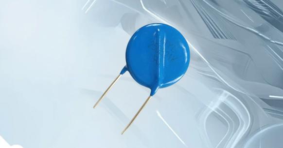
A varistor
A varistor is a voltage-limited protection device. The non-linear characteristics of the varistor allow it to clamp the voltage to a relatively fixed value when an overvoltage occurs between the two poles. This provides protection for the subsequent circuit. The main parameters of the varistor are varistor voltage, current capacity, junction capacitance, response time, etc. The symbol varistor in circuit diagrams typically indicates its placement for overvoltage protection.
2 How Does a Varistor Work?
The response time of the varistor is on the nanosecond level, which is faster than the gas discharge tube and slightly slower than the TVS tube. In general, the response speed of overvoltage protection for electronic circuits can meet the requirements. The junction capacitance of a varistor is typically in the range of hundreds to thousands of picofarads. In many cases, it should not be directly applied to the protection of high-frequency signal lines. When used to protect AC circuits, the large junction capacitance will increase leakage. It is important to consider the current when designing the protection circuit. The varistor has a larger flow capacity but is smaller than a gas discharge tube.
When the voltage applied to the varistor is lower than its threshold, the current flowing through it is extremely small, which is equivalent to a resistor with infinite resistance. When the voltage applied to the varistor is below its threshold, it is equivalent to an off-state switch.
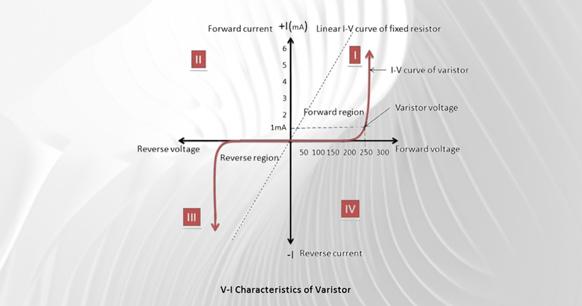
Conversely, when the voltage applied to the varistor exceeds its threshold, the current flowing through it increases sharply, which is equivalent to an infinitely small resistance. In other words, when the voltage applied to it is higher than its threshold, it is equivalent to a closed-state switch.
3 Main Parameters of the Varistor
The main parameters of the varistor are as follows: nominal voltage, voltage ratio, maximum control voltage, residual voltage ratio, current capacity, leakage current, voltage temperature coefficient, current temperature coefficient, voltage nonlinear coefficient, insulation resistance, static capacitance, etc.
- The nominal voltage refers to the voltage value across the varistor when a 1mA DC is passed. The voltage ratio is the ratio of the voltage generated when the current of the varistor is 1 mA to the voltage generated when the current of the varistor is 0.1 mA.
- The maximum limiting voltage is the highest voltage that the two ends of the varistor can withstand. The residual voltage is the voltage generated across the varistor when a specific current is flowing through it. This current value is called the residual voltage ratio. The ratio of the residual voltage to the nominal voltage is the residual voltage ratio.
- The through-current capacity is also called the through-flow capacity. It refers to the maximum pulse (peak) current allowed to pass through the varistor under specified conditions. These conditions include a specified time interval and number of times, as well as the standard inrush current.
- The leakage current and waiting current refer to the current flowing through the varistor at the specified temperature and maximum DC voltage.
- The voltage temperature coefficient refers to the rate of change of the nominal voltage of the varistor within a specified temperature range (temperature 20 ~ 70 °C). This is the change in the voltage when the current through the varistor remains constant and the temperature changes by 1 ℃.
- The current temperature coefficient refers to the relative change in the current flowing through the varistor when the temperature across the varistor remains constant and the temperature changes by 1 °C.
- The voltage non-linear coefficient refers to the ratio of static resistance value to the dynamic resistance value of a varistor under a given applied voltage. The insulation resistance refers to the resistance value between the lead (pin) of the varistor and the insulating surface of the resistor body.
- The static capacitance refers to the inherent capacitance of the varistor itself. The varistor's protection function is activated only when the voltage exceeds its threshold and the switch is closed. This surge in current has a minimal impact on other circuits, reducing the impact of overvoltage on subsequent sensitive circuits. This protection function can be used repeatedly and can also be made into a one-time protection device similar to a current fuse.
- The varistor's protection function has been widely used. For instance, the power circuit of a household color TV employs a varistor to fulfill the overvoltage protection function. When the voltage surpasses a preset threshold, the varistor exhibits its clamping characteristics. The excessive voltage is reduced to a safe level, ensuring that the subsequent circuitry operates within the designated voltage range.
- The varistor is primarily utilized for transient overvoltage protection in a circuit. However, due to its volt-ampere characteristics similar to a semiconductor Zener, it also serves a variety of circuit element functions. For instance, the varistor is a type of DC high voltage small current-voltage stabilizing element with a stable voltage of thousands of volts or more, which cannot be reached by silicon Zener. The varistor can be used in a number of different applications, including as a voltage fluctuation detection element, a DC level shifter, a fluorescent starting element, a voltage equalizing element, and so on.
4 Characteristics of a Metal-Oxide Varistor
A diode effect is formed at the junction of particles and adjacent oxides. Due to the large number of particles, it is equivalent to a large number of back-connected diodes. There is only a small reverse leakage current at low voltage. When high voltage is encountered, the diode reverse collapse occurs due to hot electrons and the tunneling effect, resulting in a significant current flow. The current-voltage characteristic curve of a metal-oxide varistor is highly non-linear, exhibiting high resistance at low voltage and low resistance at high voltage. Metal oxide varistors are currently the most common voltage clamping devices and can be used for various voltages and currents. The use of metal oxides in their structure makes them highly effective in absorbing short-term voltage transients and capable of handling higher energy levels.
Metal-oxide varistors (MOVs) function similarly to ordinary varistors, conducting at a certain voltage and stopping when the voltage drops below the threshold. However, there are notable differences between the standard silicon carbide (SiC) varistor and the MOV. One key distinction is the low leakage current of the zinc oxide material through the MOV under normal operating conditions. Additionally, the MOV's operating speed is much faster in the clamping transient.
MOVs typically feature radial leads and a hard outer blue or black epoxy coating, which is similar to that found on disc ceramic capacitors. This allows for physical mounting on circuit boards and PCBs in a manner that is straightforward and efficient. The structure of a typical metal-oxide varistor is as follows:
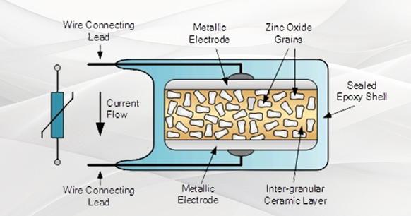
Metal oxide varistor structure
Selecting the appropriate MOV for input line or phase transients can be more challenging due to the inherent uncertainty surrounding the characteristics of the power supply. In such cases, the protection of MOV selection circuit power transients and spikes often relies on informed estimation.
Metal-oxide varistors can be used for a variety of voltages, from about 10 volts to more than 1000 volts AC or DC. This makes them suitable for use in a wide range of applications. When choosing between an MOV and a silicon varistor, it is important to consider the supply voltage. The maximum continuous root-mean-square voltage rating of the MOV or silicon varistor should be slightly higher than the highest expected power supply voltage. For instance, a 120-volt power supply is 130 volts RMS, while a 230-volt supply is 260 volts RMS.
The maximum surge current value that the varistor will use depends on the transient pulse width and the number of pulse repetitions. It is reasonable to assume that the width of the transient pulse is usually 20 to 50 microseconds (μs) long. If the peak pulse current rating is insufficient, the varistor may overheat and be damaged. Therefore, if the varistor operates without any failure or degradation, it must be able to quickly dissipate the absorbed energy of the transient pulse and safely return to its pre-pulse state.
5 How to Test a Varistor?
- Before measuring the resistance of a varistor, it is important to connect the two test leads (regardless of positive and negative) to the two ends of the resistor. This will ensure an accurate measurement. To improve the measurement accuracy, it is necessary to select the appropriate range according to the nominal value of the measured resistance. Due to the non-linear relationship of the ohm scale, it is important to note that when reading the resistance value, the pointer deflection angle should not be less than 1/3 of the full scale. Otherwise, it is necessary to switch the range. The varistor cannot be directly measured using a multimeter's ohm range.
- Use a megohmmeter to measure the leakage resistance. The leakage resistance is typically higher than 10 MΩ.
- Use the resistance gear of the multimeter to test the forward and reverse resistance values of the varistor and compare them with the nominal resistance values to determine whether the varistor is good or bad.
A multimeter
6 Varistor Component in Circuits
The varistor component is essential for protecting electronic devices and circuits from transient voltage surges. By clamping excessive voltage, it prevents damage to sensitive components and ensures the longevity and reliability of the circuit. Varistors are commonly used in power supply circuits, communication lines, and various other applications where voltage spikes may occur.
In summary, varistors are versatile and crucial components for overvoltage protection. Understanding their function, parameters, and testing methods is essential for designing and maintaining reliable electronic circuits.