How Inductors Work: Principles, Types, and Applications Explained
Inductors store electrical energy as magnetic energy. They are similar to transformers but have only one winding. Inductors have a skeleton, winding, shield, packaging material, iron core, and magnetic core.
Inductors Explained - The basics how inductors work working principle
Catalog
1 Introduction
2 The unit of inductance
3 What is the function of an inductor?
1)The role of inductors in alternating current
2)The role of inductors in inductance filtering
4 How do inductors work?
1 Introduction
Inductors are amazing energy storage elements that convert electrical energy into magnetic energy for storage. It's similar to a transformer, but the inductor has only one winding, which makes it even more special! An inductor is an amazingly versatile component that can be constructed in a variety of ways. The most common structure is a skeleton, a winding, a shield, the packaging material, an iron core, and a magnetic core. An inductor is an amazing passive electronic component that can store electrical energy in the form of magnetic flux! When current flows, a magnetic field is generated on the right side of the current flow direction, which is really quite an amazing phenomenon! In its most basic form, an inductor can be as simple as a wire coil, which is a great place to start! By making wires around the core, you can easily double the inductance value! The material characteristics of the magnetic core have a significant impact on the inductance value, and the characteristics of the inductance can also be optimized through the shape.
Inductors are an amazing tool for engineers who want to manage energy and control signals. Let's dive into the world of inductors! These amazing devices have so many fascinating characteristics.
The inductor is a fascinating device that differs from the resistor in one crucial way: the electrical energy related to the induced current is stored in the relevant magnetic field, rather than dissipated in the form of heat. This means that the inductor can be used to store energy, which is a very useful property.
Another interesting aspect of the inductor is that when the inductor current is interrupted, it will return to the circuit. This is a very useful property as it means that the inductor can be used to create a kind of switch.
The inductor also has a relationship with frequency, which is another fascinating aspect of its behaviour. When the magnetic field stores the energy it can accommodate, the inductor will "saturate". This is an important property as it means that the inductor can be used to regulate the flow of energy. And then, when there's an increase in current, the strength of the magnetic field won't change, and any excess electrical energy will be dissipated as heat.
These characteristics make inductors the perfect choice for simulating filter circuits and managing the energy flow in switching power conversion applications.
2 The unit of inductance
The unit of inductance was first discovered by the American scientist Joseph Henry. Since then, it has been known as the "Henry" unit. The unit of inductance is called the Henry (H). If a current with a rate of change of 1 amp/sec produces a back EMF (back voltage) of 1 volt, this device or circuit has an inductance of 1H. The symbol for the inductor is the capital letter L. The unit of inductance is H, mH, and μH. I'm happy to help you with this! Their conversion relationship is: One H is equal to 10³ mH, and 10⁶ μH.
When you apply a voltage across the inductor, you'll see that the rate of current rise depends on the voltage and the inductance value. If you apply 1V to the 1H inductor, you'll see the current increase by 1A every second. I'm so happy to tell you that the formula you need is V=L*di/dt. A current of 1A through a coil can produce a magnetic flux of 1Wb, so this coil has an inductance of 1H. Isn't that fascinating?
And there are also general inductors and precision inductors, as shown below.
|
|
Precision inductor |
General inductor |
||||
|
Symbol |
F |
G |
J |
K |
L |
M |
|
Tolerance |
1% |
2% |
5% |
10% |
15% |
20% |
3 What is the function of an inductor?
1. The role of inductors in alternating current
When alternating current flows into the inductor, it acts to hinder its change. This process occurs gradually, rather than instantaneously. When the AC power is off, the alternating current inductor will not lose its capacity immediately, but will gradually become smaller. This can be observed through the change in brightness of an incandescent lamp. In an AC circuit, inductors, incandescent lamps, switches, and other components are connected in series. When the switch is closed, the incandescent lamp will not turn on instantly, but will gradually brighten. When the switch is off, the incandescent lamp will not suddenly turn off. Instead, it will gradually darken. This process demonstrates the inductor's role in stabilizing the current. The conversion of electric energy into magnetic energy and then back into electric energy is a fundamental process in the operation of inductors. In the first instance, the inductor acts as a lamp, transforming darkness into brightness. In the second, it acts as a filter, regulating the flow of current.
2. The role of inductors in inductance filtering
In a DC circuit, when a current flows through the inductor, an induced magnetic field is generated in the coil instantaneously, inducing a current in the magnetic field. The direction of the induced current and the current flowing through the inductor is opposite, which impedes the flow of external current. The flowing current is stabilized, and the induced magnetic field remains unchanged, allowing the DC current to flow smoothly.
From this process, it is evident that the inductance impedes the change of current. When alternating current is present, the inductance resists the alternating current's change in flow.
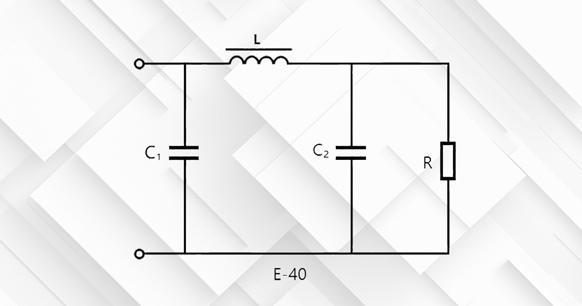
Figure1. π-type filter circuit
In a DC circuit, the flow of current through the inductor generates an induced magnetic field in the coil, which in turn induces a current in the magnetic field. The direction of the induced current and the current flowing through the inductor is opposite, which impedes the flow of external current. The current flow is stabilized, and the induced magnetic field remains unchanged, allowing the DC current to flow smoothly.
This process demonstrates that inductance impedes the change of current. When alternating current is present, the inductance resists the alternating current's change in flow.
4 How do inductors work?

Figure 2 illustrates the basic structure of an inductor.
In the circuit diagram, the inductor is represented as follows
: 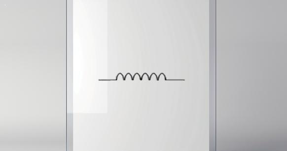
Figure3. Inductor symbol
When current flows through the wire, a concentric magnetic field is generated around the wire. If the wire is bent into a "spring shape" as shown in the figure, the magnetic flux inside the inductor will point in the same direction, thereby strengthening the magnetic field. By adjusting the number of turns, a magnetic field proportional to the number of turns can be generated. This is the principle of the inductor.
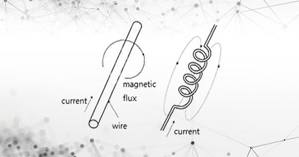
Figure4. Principle of inductor
A magnetic field is generated when current passes through an inductor. Conversely, the magnetic field changes will produce a current. (Electromagnetic induction law)
E = L ・(d i/d t)
L: Self-inductance of inductor
E: Back EMF
The back electromotive force E generated in the inductor is proportional to the rate of change of current per unit time (di/dt), so it does not occur when a certain current continues to flow in the same direction of direct current. In other words, the inductor has no effect on the DC current, but only on the AC current to block the current. This property of an inductor allows it to be used as a resistance (impedance) in an AC circuit. The impedance Z (unit Ω) of the inductor is:
Z=ωL=2πfL
f is the AC frequency and L is the self-inductance of the inductor.
An inductor is a passive electronic component that can store electrical energy in the form of magnetic flux. Typically, the wire is wound, and when a current passes, a magnetic field is generated from the right side of the direction of current flow.
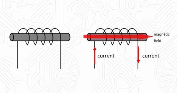
Figure5. Inductor magnetic field
The calculation formula for the inductance value is shown below. The greater the number of rolls, the stronger the magnetic field. At the same time, increasing the cross-sectional area or changing the magnetic core can enhance the magnetic field. The calculation formula for the inductance value is as follows:
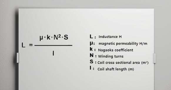
Figure6. The calculation formula of the inductance value
Let us examine the effects of alternating current on the inductor. Alternating current is defined as a current whose magnitude and direction change periodically with time. When an alternating current passes through the inductor, the magnetic field generated by the current cuts off the other windings, thus generating a reverse voltage, which hinders the current change. In particular, when the current suddenly increases, an electromotive force in the direction opposite to the current, that is, in the direction of the current decrease, will be generated to hinder the increase of the current. Conversely, when the current is reduced, it is generated in the direction of the increasing current.
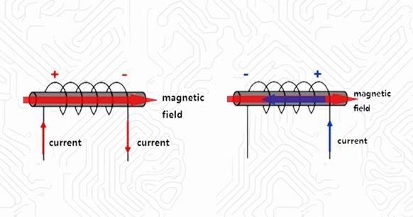
Figure7. AC current flows through the inductor
In the event that the direction of the current is reversed, a reverse voltage will also be generated. Prior to the current being blocked by the reverse voltage, the current flow will be reversed, preventing the current from flowing. Conversely, direct current remains unaltered by the current, thus eliminating the potential for a reverse voltage and the associated risk of short circuits. In other words, an inductor is a component that allows direct current to pass, but not alternating current.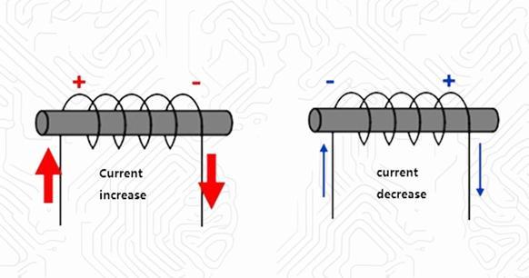
Figure8. Reverse current flows through the inductor
The following figure will help you understand how the inductor works in the circuit:
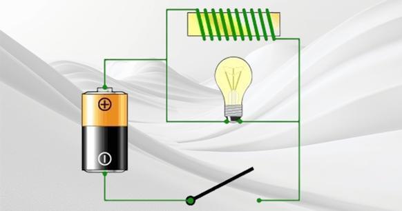
Figure9. inductor works in the circuit
The components of this device are a battery, a light bulb, a coil around the yellow iron block, and a switch. The coil is the inductor. If you have read the working principle of the electromagnet, you will be aware that the inductor is an electromagnet.
If the inductor is removed from the circuit, a standard flash will result. Once the switch is closed, the bulb will illuminate. If the inductor is installed in the circuit as shown, its role will be entirely different.
The light bulb is a resistor, which generates heat and causes the filament to shine. The resistance of the wire in the coil is significantly lower than that of a resistor, as it is merely a wire. When the switch is activated, the light bulb will glow dimly. The majority of the current will flow through the loop via the low-resistance path. The actual result is that when the switch is closed, the light bulb is initially bright and then dims. Upon activation of the switch, the light bulb reaches a high brightness level and then rapidly declines.
The inductor is responsible for this peculiar phenomenon. Once current begins to flow in the coil for the first time, the coil forms a magnetic field. During the formation of the magnetic field, the coil acts to prevent the flow of current. Once the magnetic field is formed, the current can normally pass through the wire. When the switch is opened, the magnetic field around the coil causes current to flow in the coil until the magnetic field disappears. This current can maintain the bulb's illumination for a period of time even when the switch is open. In other words, an inductor can store energy in its magnetic field and typically prevents any change in the amount of current flowing through it.
Consider the analogy of water flow.
To gain an intuitive understanding of the working principle of an inductor, consider the following analogy. Imagine a narrow water pipe with water flowing through it, and a heavy water wheel with a paddle immersed in the water pipe. Initially, the water in the pipe does not flow. Now, attempt to make the water flow. The water wheel will stop the flow of water until it turns with the speed of the water. If you attempt to halt the flow of water in the pipe, the rotating water wheel will continue to move the water until the speed of the water wheel is reduced to the speed of the water flow. The working principle of the inductor is analogous, in that electrons flow in the wire, and the inductor prevents the flow of electrons from changing.


