
Comprehensive Guide to Photoresistors: Symbols, Circuits, and Material Differences

The article presents the main characteristics and principles of the photoresistor, including its working and structural principles. There are three types of photoresistor: ultraviolet photoresistors, infrared photoresistors, and visible light photoresistors. The photoresistor is used in two main applications: dimming circuits and light switches.
Light Dependent Resistors (LDR): Working Principle
Abstracts
There are three types of photoresistor: ultraviolet photoresistors, infrared photoresistors, and visible light photoresistors. Commonly used materials include cadmium sulfide, selenium, aluminum sulfide, lead sulfide, and bismuth sulfide. The photoresistor's operational principle is based on the internal photoelectric effect. Photosensitive resistors are manufactured by affixing electrode leads at both ends of the semiconductor photosensitive material within a transparent tube case. The photoresistor is used in two applications: dimming circuits and light switches.
I. Introduction
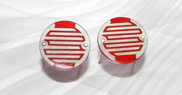
Figure 1. Photoresistor
The photoresistor is also known as the light-dependent resistor (abbreviated as LDR) or photoconductor. Commonly used materials include cadmium sulfide, selenium, aluminum sulfide, lead sulfide, and bismuth sulfide. These manufacturing materials exhibit a unique property whereby the resistance value decreases rapidly under the irradiation of light of a specific wavelength. This is due to the fact that the carriers generated by the light all participate in the conduction process and undergo a drift movement under the influence of an external electric field. The photoresistor's resistance decreases rapidly as electrons move to the positive pole of the power supply and holes move to the negative pole.
A photoresistor is a specialized resistor manufactured using semiconductor materials, such as sulfurized or selenized spacers. Its operational principle is based on the internal photoelectric effect. The resistance value decreases as the intensity of the light source increases. As light intensity increases, the resistance value decreases rapidly, with the brightest resistance value reaching as low as 1KΩ. The photoresistor is highly sensitive to light. In the absence of light, the photoresistor is in a high-resistance state, with a dark resistance of up to 1.5MΩ.
The photoresistor is a type of resistor that employs the photoconductive effect of a semiconductor to alter its resistance value in accordance with the intensity of incident light. It is also known as a photoconductive detector. The intensity of the incident light is reduced, resulting in a reduction in resistance. Conversely, when the intensity of the incident light is weak, the resistance increases. We also offer another type of photoresistor. When the intensity of the incident light is low, the resistance is reduced. Conversely, when the intensity of the incident light is high, the resistance is increased.
Photoresistors are typically employed in light measurement, light control, and photoelectric conversion (converting changes in light to changes in electricity). A common photoresistor is the cadmium sulfide photoresistor, which is made of semiconductor material. The photoresistor's sensitivity to light (that is, its spectral characteristics) is very close to the human eye's resCdponse to visible light (0.4 ~ 0.76) μm. When designing the light control circuit, the light of incandescent bulbs (small electric beads) or natural light is used as the control light source, which greatly simplifies the design.
II. Specifications
In general, photoresistors are manufactured in sheet form to enhance their light-absorbing capabilities. When exposed to light, the semiconductor wafer (photosensitive layer) generates an electron-hole pair, enabling it to participate in conduction and increase the current in the circuit. To achieve high sensitivity, the electrode of the photoresistor frequently employs a comb-like pattern, which is created through vapor deposition of a metal such as gold or indium on a photoconductive film beneath a specific mask. The following diagram illustrates the typical structure of a photoresistor.
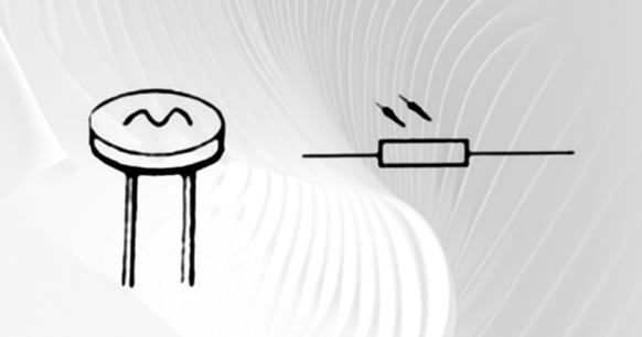
Figure 2. Structure of a general photoresistor
A photoresistor typically comprises a photosensitive layer, a glass substrate (or a resin moisture-proof film), and electrodes. Photoresistors are represented by the letters "R" or "RL," "RG" in the circuit, which are the photoresistor symbols used to denote their function as light-sensitive resistors.
A photoresistor is composed of cadmium sulfide (CdS). Often referred to by the abbreviation CdS photoresistor, this component is widely recognized for its light-sensitive properties. The product is available in two packaging options: epoxy resin and metal. Both options are wire-type (DIP). Epoxy-packaged photoresistors are available in diameters of 3mm, 4mm, 5mm, 7mm, 11mm, 12mm, 20mm, and 25mm, according to the ceramic substrate diameter.
III. Parameter & Characteristics
The photoresistor is divided into three types according to its spectral characteristics: ultraviolet, infrared, and visible light.
1. The main parameters are as follows:
(1) Photocurrent and bright resistance. When a certain applied voltage is present, the current flowing is called the photocurrent. This is in response to light irradiation, and the ratio of the applied voltage to the photocurrent is called the bright resistance, which is usually expressed by "100LX."
(2) Dark current and dark resistance. When there is no light, the photoresistor is known as the dark current. The ratio of the applied voltage to the dark current is called the dark resistance, and it is usually expressed as "0LX." This measurement is taken with an illuminance meter, and its unit is lux lx.
(3) Sensitivity Sensitivity refers to the relative change in the resistance value (dark resistance) when the photoresistor is not illuminated by light and the resistance value (bright resistance) when illuminated by light.
(4) Spectral response. The spectral response is also known as spectral sensitivity, which refers to the sensitivity of the photoresistor when exposed to monochromatic light with varying wavelengths. By plotting the sensitivity at different wavelengths, you can obtain a curve representing the spectral response.
(5) Illumination characteristics The illumination characteristics refer to the electrical signal output by the photoresistor as a function of illumination. As illustrated in the light characteristic curve of the photoresistor, an increase in light intensity is accompanied by a rapid decrease in the resistance value of the photoresistor. As the light intensity is increased further, the change in resistance value initially decreases, before gradually becoming gentle. In the majority of cases, this characteristic is non-linear.
(6) Volt-ampere characteristic curve The relationship between voltage and current applied across the photoresistor under a specific illumination is defined as the volt-ampere characteristic. It can be observed that at a given bias, the greater the light intensity, the larger the photocurrent. It can be observed that, under a specific light intensity, the larger the voltage applied, the larger the photocurrent. However, it should be noted that the voltage cannot be increased indefinitely, as any photoresistor is limited by the rated power, the maximum operating voltage, and the rated current. It is important to note that exceeding the maximum operating voltage and maximum rated current may result in permanent damage to the photoresistor.
(7) Temperature coefficient. It should be noted that the photoelectric effect of the photoresistor is significantly influenced by temperature. Some photoresistors demonstrate enhanced photoelectric sensitivity at lower temperatures, but this sensitivity diminishes at higher temperatures.
(8) Rated power The term "rated power" refers to the maximum amount of power that a photoresistor can consume within a given circuit. As the temperature rises, the power consumption of the device in question will decrease.
2. Frequency Characteristics
When the photoresistor is irradiated with pulsed light, the photocurrent takes a period of time to reach a stable value. Once the light source is terminated, the photocurrent does not immediately reach zero. This is a characteristic of the photoresistor and is known as the time delay. Due to the differing photosensitivity and resistance delay characteristics of different materials, their frequency characteristics are also different. While lead sulfide is used more frequently than cadmium sulfide, the delay of most photoresistors is relatively large, limiting its suitability for applications requiring fast response times.
IV. Please describe the operation of the photoresistor.
1. The photoresistor's working principle is based on the internal photoelectric effect. Photosensitive resistors are manufactured by affixing electrode leads at both ends of the semiconductor photosensitive material and encasing them in a tube case with a transparent window. To enhance sensitivity, the two electrodes are frequently crafted into a comb configuration. The materials used to manufacture photoresistors are primarily semiconductors, including metal sulfides, selenides, and tellurides. A variety of techniques, including coating, spraying, sintering, and others, are employed to create a photoresistor with a very thin profile and a comb-shaped ohmic electrode on an insulating substrate. The leads are connected and sealed in a sealed housing with a light-transmitting mirror to prevent moisture from affecting the sensitivity. Once the incident light has ceased, the electron-hole pairs generated by the photon excitation will recombine, restoring the photoresistor's resistance to its original value. When a voltage is applied to the metal electrodes at both ends of the photoresistor, a current will pass through it. When the photoresistor is exposed to light with a specific wavelength, the current will increase in direct correlation with the light intensity, thereby achieving photoelectric conversion. The photoresistor has no polarity and is purely a resistive device. It can be used with both DC voltage and AC voltage. The conductivity of a semiconductor is dependent on the number of carriers in the semiconductor's conduction band.
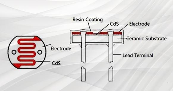
Figure 3. Photoresistor schematic
2. Structural Principle
Photoresistors are a special type of resistor made of vulcanized or selenized semiconductor materials. Additionally, the surface is coated with a moisture-proof resin that has a photoconductive effect. The photoresistor's operational principle is based on the internal photoelectric effect. This involves mounting the electrode leads at both ends of the semiconductor photosensitive material, and forming the photoresistor by packaging it in a tube case with a transparent window. To enhance sensitivity, the two electrodes are frequently designed in a comb-shaped configuration.
The conductivity of a semiconductor is dependent upon the number of carriers present in the semiconductor's conduction band. When the photoresistor is illuminated, the electrons in the valence band absorb the photon energy, resulting in a transition to the conduction band where they become free electrons. Concurrently, the generation of holes occurs. The formation of an electron-hole pair results in a reduction in resistivity. The greater the intensity of the light, the more photo-generated electron-hole pairs and the lower the resistance value. When a voltage is applied across the photoresistor, the current flowing through the photoresistor increases in direct proportion to the intensity of the light. The incident light is absorbed, the electron-hole pair recombines, the resistance returns to its original value, and the current decreases.
The photoresistor is highly sensitive to light. In the absence of light, the photoresistor is in a high-resistance state, with a dark resistance of up to 1.5MΩ. When there is light, the material is excited, resulting in the generation of free electrons and holes. This causes a decrease in the resistance value. As light intensity increases, the resistance value decreases rapidly, with bright resistance values reaching as low as 1KΩ.
The lighting characteristics of the photoresistor are non-linear in most cases, with a small range where they are linear. Additionally, the resistance value of the photoresistor exhibits a high degree of dispersion, with significant resistance changes and irregularities across a wide range.
The sensitivity of the photoresistor is defined as the relative change in the resistance value (dark resistance) of the photoresistor when it is not exposed to light and the resistance value (bright resistance) when it is exposed to light. The ratio of the dark resistance to the light resistance of the photoresistor is approximately 1500:1. The larger the dark resistance, the more suitable the photoresistor. It is recommended that a DC or AC bias voltage be applied to the photoresistor. The MG photoresistor is suitable for use with visible light. The MG photoresistor is used in a variety of applications, including automatic control circuits, photoelectric counting, photoelectric tracking, light control, electric lamps, automatic exposure of cameras, and automatic brightness control circuits of color televisions.
V. Classification
Divided by semiconductor material: intrinsic photoresistor, doped photoresistor. The latter has proven to be a reliable and high-performing option, making it the preferred choice for many applications.
The photoresistor can be divided into three types based on its spectral characteristics:
1. Ultraviolet photoresistors are more sensitive to ultraviolet light, including cadmium sulfide and cadmium selenide photoresistors.
2. Infrared photoresistors are primarily composed of lead sulfide, lead telluride, and lead selenide. Photosensitive resistors, such as indium antimonide, are utilized in a variety of applications, including missile guidance, astronomical detection, non-contact measurement, human lesion detection, infrared spectroscopy, infrared communications, and other defense, scientific research, and industrial and agricultural production.
3. Visible Light Photoresistor: This category includes selenium, cadmium sulfide, cadmium selenide, cadmium telluride, gallium arsenide, silicon, germanium, and zinc sulfide photoresistors. It is primarily utilized in a multitude of photoelectric control systems, including the photoelectric automatic opening and closing of portals, the automatic turning on and off of navigation lights, street lights, and other lighting systems, the automatic water supply and automatic water stopping devices, mechanical automatic protection devices, and "position detectors," camera automatic exposure devices, photoelectric counters, smoke alarms, photoelectric tracking systems, and so forth.
VI. Application
The photoresistor is a semiconductor light-sensitive device with a variety of applications. In addition to its high sensitivity, fast response speed, good spectral characteristics, and good R-value consistency, this product can maintain high stability and reliability in harsh environments with high temperature and humidity. It is suitable for use in a wide range of applications, including cameras, solar garden lights, lawn lights, currency detectors, quartz clocks, music cups, gift boxes, mini night lights, photoacoustic control switches, street light automatic switches, and various light control toys, light control lighting, lamps, and other light automatic switches. Please find below a few typical application circuits.
1. Dimming circuit
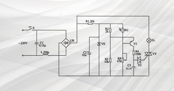
Figure 4. typical light-control dimming circuit
Figure 4 illustrates a typical light-control dimming circuit. The working principle is as follows: when the surrounding light becomes weak, the resistance of the photoresistor increases, thereby raising the voltage applied to the capacitor C. This increases the voltage across the lamp, achieving the desired result. Conversely, if the surrounding light becomes brighter, the resistance value of RG will decrease, which will cause the conduction angle of the thyristor to decrease, and the voltage across the lamp will also decrease at the same time.
The rectifier bridge in the above circuit must be capable of handling a DC pulsating voltage, which cannot be filtered by a capacitor into a smooth DC voltage.
2. Light Switch
There are numerous types of light-controlled switch circuits with relay-controlled output that utilize photoresistors as core components. These include self-locking bright excitation, dark excitation, precision light excitation, and dark excitation. Please find below several typical circuits.
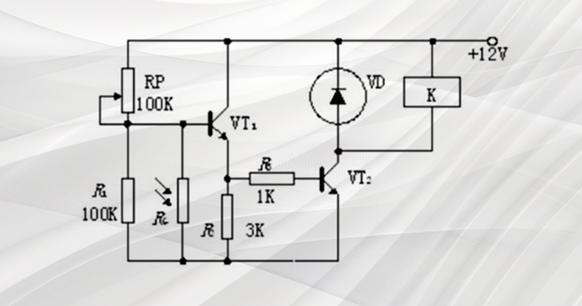
Figure 5. simple dark-excitation relay switching circuit
Figure 5 illustrates a straightforward dark-excitation relay switching circuit. The working principle is as follows: when the illuminance drops to the set value, VT1 is turned on due to the rise of the resistance of the photoresistor. This in turn makes the VT2 excitation current flow, which causes the relay to operate. The normally open contact is closed, and the normally closed contact is opened, thus enabling external circuit control.
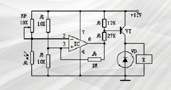
Figure 6. precision dark-excitation time delay relay switch circuit
Figure 6 illustrates a precision dark-excitation time delay relay switch circuit. The circuit's working principle is as follows: when the illuminance drops to the set value, the potential of the inverting terminal of the operational amplifier IC increases due to the rise of the resistance of the photoresistor. This in turn excites the VT to turn on. The VT excitation current initiates the relay operation, closing the normally open contact. The normally closed contact is opened to enable control of the external circuit.
VII. Advantages and Disadvantages
1. Advantages:
(1) The internal photoelectric effect has no connection to the electrode, only the photodiode is involved, so a DC power supply can be used.
(2) Sensitivity is related to the semiconductor material and the wavelength of the incident light.
(3) Coated with epoxy, it has good reliability, a small volume, a small sensitivity, a quick response, and a good spectrum characteristic.
2. The product has the following disadvantages:
(1) The photoelectric conversion is less linear under strong light;
(2) The photoelectric relaxation process is longer. After light irradiation, the photoconductance of semiconductors gradually rises with the illumination time, reaching a steady-state value after a period of time. Once the light source is no longer present, the photoconductivity gradually decreases.
Furthermore, the device has a low frequency response, meaning it is unable to detect rapidly changing light signals. This is an important consideration when comparing photodiode vs photoresistor, as photodiodes offer higher sensitivity and are better suited for detecting quick fluctuations in light. The delay time is affected by the light intensity of the incident light, ranging from milliseconds to seconds. The photodiode does not have this disadvantage, as it has higher sensitivity than the photoresistor.
VIII. Conclusion:
The photoresistor is an essential component in photoelectric conversion. The rapid development of electronic information technology and the continuous enhancement of the performance requirements of electronic components will greatly benefit from the automation of photoresistor production, which will facilitate the further development of industrialization.