Building a Resistor Color Code Calculator and Ohmmeter Using Arduino
For our project, we are going to create an Arduino-based ohmmeter that also functions as a resistor color code calculator visually modeled after the All About Circuits’ popular online Resistor Color Code Calculator. Here is a video of our finished project in operation:
Project Overview
The brains of this system is an ATmega328 microcontroller (Arduino UNO). We will also use:
- A small TFT LCD display.
- Six push buttons for interacting with a simple GUI,
- A CD4051 multiplexer/demultiplexer
- Eight different resistors for switching between measurement ranges.
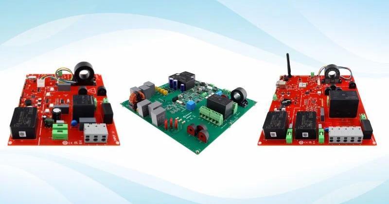
Similar to several of my previous projects, I’ve created a dedicated All About Circuits branded PCB for this device; however, you could also replicate this project using a breadboard or perfboard.
This project is designed to be fun and educational. There are far more accurate and reliable methods of testing your components, as even the cheapest multimeters will probably give you better results. The typical resistors have a tolerance of 5%, and the ATmega328’s analog-to-digital converter (ADC) has a resolution of only 10 bits. So, our accurate is going to be less than a good ohmmeter.
Resistor Color Codes
Initially developed by the Radio Manufacturers Association in the 1920s, the resistor color code system is used to provide a visual indication of a resistor's value and rating (Figure 1).
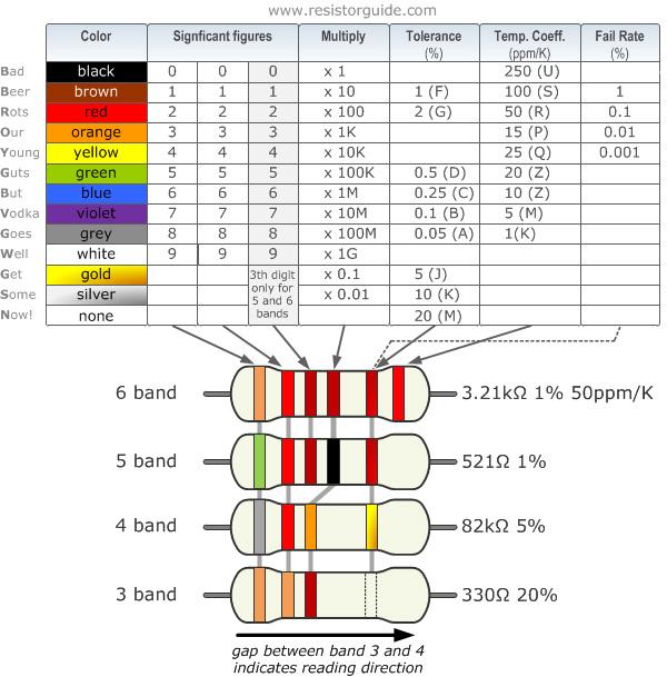
Figure 1. Resistor color code chart. Image used courtesy of EEPower
The color code calculator that we are going to build in this project covers only four band resistors. For these types of components, the first two bands represent the two most significant digits of the resistance value, the third band represents a decimal multiplier, and the fourth band represents the tolerance of value in percent.
What Is an Ohmmeter?
A vital tool in every EE lab, the ohmmeter is an instrument for measuring electrical resistance found either as a dedicated unit or as part of a multimeter. It requires an internal voltage source in order to create the necessary operational current, as well as appropriate ranging resistors for effective measurements of the device under test.
Although there are various different types of ohmmeters, this project uses a simple voltage divider. A voltage divider is a circuit where an input voltage across two resistors connected in series is scaled down proportional to the ratio of the two resistors.
We are going to switch between multiple ranging resistors (known value) connected in series to the resistor that’s being tested (unknown value) and calculate its value based on the measured output voltage and known input voltage using Ohm’s Law.
Circuit Design
The schematic of Figure 2 shows us how to wire all of our components together for a breadboard or PCB version of this project. If you're using a development board, make sure that your components match the pin configuration in the code.
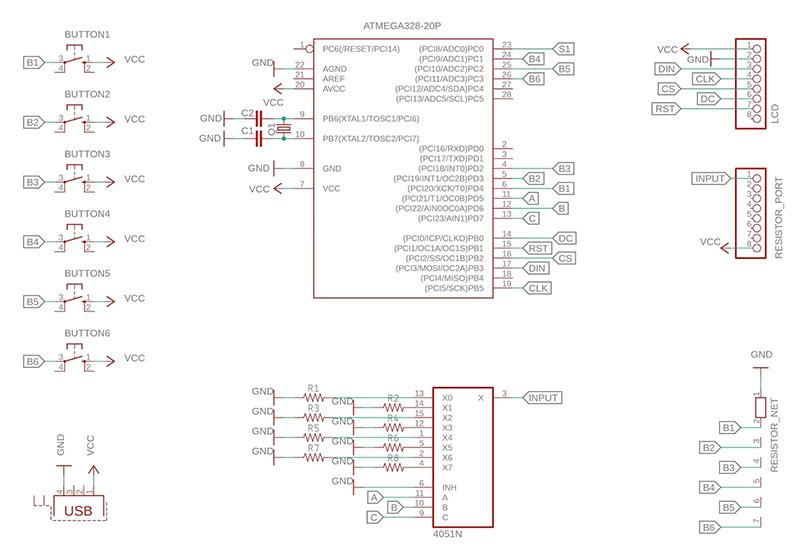
Figure 2. Schematic for the resistor color code calculator and ohmmeter.
Since I’m not using a voltage regulator, it’s best practice to use this device plugged into a regulated 5 V source. My PCB uses a dedicated USB B port which can plug into a computer, phone charger, or power bank, which also makes it portable.
Graphical Display and User Interface
Our system uses a series of seven nested screens (dedicated functions) capable of appearing on the 128x160 TFT LCD, which serves as its rudimentary graphical user interface (GUI). The illustrations for these screens are generated by directly drawing alphanumerics and basic shapes onto the display using Adafruit’s GFX and ST7735 library. The ST7735 is a display driver chip embedded into the 1.8-inch TFT LCD module used in this project.
Note: Combining shapes as graphics is done because using large bitmaps converted into Arduino code would impair system performance.
Controls
Each screen function of our GUI is capable of responding to up to six tactile push buttons. On the dedicated PCB, the outer two are marked as “Select” and “Back,” while the inner four are marked with arrow symbols for left, right, up, and down. These buttons form the controls for navigating through menus, selecting menu items, and returning to the previous screen.
Main Menu
The initialization screen serves as its main menu. This portion of the GUI prompts the user to choose between one of the two primary functions – ohmmeter or color code calculator (Figure 3). For this menu, I decided to place an All About Circuits logo just above the two menu items, recreated using a couple of interconnected rounded rectangles.
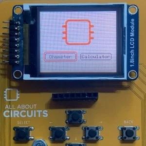
Figure 3. Main menu for ohmmeter and resistor color code calculator function selection.
Navigation and Selection
Each screen of our system contains multiple selectable menu items displayed as rounded rectangles. To navigate through these items, there’s an additional outline rectangle for every menu that can be shifted either up or down using the four navigation buttons.
By clicking the “Select” button within a menu, our code determines what item from that menu has been selected by the user by checking the current position of the outline rectangle as well as the corresponding outlined item.
Switching between menus is internally implemented using a flag variable that keeps track of what needs to be displayed on the LCD according to the user’s selection. That is, which one of the seven screen functions needs to be called in the next iteration of the Arduino code loop.
Ohmmeter App
The second screen in our system is the self-contained ohmmeter app as shown in Figure 4. The top of this screen displays the value of the measured resistor as well as the selected measurement range. The bottom of the screen displays eight selectable ranges corresponding to the values of each ranging resistor connected to the outputs from the CD4051 chip.
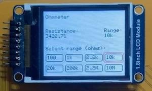
Figure 4. Ohmmeter home screen.
In our project, we’re using the CD4051 as a demultiplexer and address it using three pins from the ATmega328. Doing so will allow us to digitally select one out of the eight CD4051 output channels, physically connecting a ranging resistor to the unknown resistor on its input, thus completing our voltage divider circuit.
Once a range is selected from the GUI, the microcontroller will address the demultiplexer and measure the output voltage from the voltage divider on one of its analog pins. From here, it calculates the unknown resistance according to the formula discussed previously and displays its measured value on the system’s LCD.
In order to understand how to properly choose or calibrate measurement ranges, you should check out AAC’s Intro Lab – How to Use an Ohmmeter to Measure Resistance article.
Resistor Color Code Calculator App
The third screen in our system is the Resistor Color Code Calculator app (Figure 5). This screen is split into three sections and can take the user to four additional nested menus.
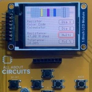
Figure 5. Resistor color code calculator home screen.
The top section of this screen illustrates a four-band resistor modeled after the All About Circuits’ Resistor Color Code Calculator, which was recreated using a series of different size and color rectangles. On this graphic, the four rectangles representing the resistor’s color bands are capable of dynamically switching their color based on user input.
The bottom right section contains four menu items, one for setting each of the color bands that take the user to an additional menu screen, while the bottom left section contains the app title, as well as the calculated results (resistance value and tollerance) for the selected color band sequence.
In order to set a color band, the user must first enter one of the four additional menu screens. These screens consist of an appropriate title as well as a selection of colors or menu items depicted underneath it (as shown in Figure 6). Every time the user selects a color from one of these menus, the system saves it for that specific band, returns to the previous screen, changes the color of that band on the resistor illustration, and inputs its value into the color code calculator formula.
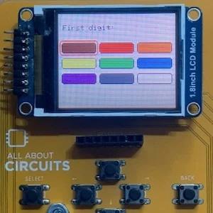
Figure 6. Resistor color code calculator first digit color band selection screen.
With this, the resistance and tolerance of the currently depicted band sequence on the illustrated resistor is calculated and displayed at the bottom left section of our Resistor Color Code Calculator screen.
Uploading the Code
Once you've wired everything up you need to upload the code to your microcontroller. If you’re using a regular Arduino or similar development board, this process is straightforward, just plug in the USB connector, select your board along with the appropriate com port, and click on the upload button. You can download the Arduino code from Github.
On the other hand, If you wish to recreate this project as a standalone system using my PCB design, you need an additional USB to Serial module in order to program the ATmega328 IC by following Arduino’s From Arduino to a Microcontroller on a Breadboard article.